Connection diagram for a two-button switch for two light bulbs: electrical installation features
Carrying out electrical installation work yourself can save a lot of money and time.To perform such operations, you need to study their features, execution order, etc.
It is these issues that we will deal with in our article, considering the features of electrical installation work. The information is presented in the form of step-by-step instructions, accompanied by detailed photos that illustrate the step-by-step installation process.
And although the wiring diagram for a two-button switch for two light bulbs may seem complicated at first, once you understand the principle of operation of such a device, even a novice electrician can handle the installation.
The content of the article:
General information about the two-key switch
A switch of this type is most often used for lighting in two adjacent rooms or for controlling a multi-arm chandelier. The first option is traditionally used for a separate bathroom or for lamps installed in different rooms.
If it is convenient to turn on both lighting devices from one point, it is more reasonable to install one device with two keys, rather than two identical single-key switches.
If you organize the control of a chandelier in this way, you can regulate the illumination of the room by turning on only some of the light bulbs or all at the same time. Such a scheme can also be useful in the kitchen, for example, to turn on the upper and lower lights.
It may not be easy for a less experienced master to understand with diagrams and the order of connecting a switch with two keys. But if you understand the principle and sequence of work, then there will be no problems.
Switch installation features
Let's assume that our task is to equip a new building with electrical wiring that has not yet been touched by an electrician. Let's consider the features of performing electrical installation work in stages.
Stage #1 - performing preparatory work
First you need to prepare the necessary tools and materials:
- single-pole circuit breaker and RCD;
- switch with two keys;
- distribution box;
- two lamps;
- din - rail to install devices to protect wiring and owners;
- socket box suitable in size and type;
- electrical cable;
- electrical tape;
- perforated tape for cable installation;
- fasteners;
- screwdrivers, Phillips and flat, or a screwdriver with attachments;
- voltage indicator;
- knife, wire cutters, pliers, etc.
The connection begins with the preparatory stage. First you need to install a distribution box in which all the wires will be collected and connected in accordance with the diagram.
To protect the circuit from breakdowns and overloads, you will need an automatic circuit breaker, and to protect the owners of the premises from shock in the event of a current leak, you will need an RCD. These devices must be installed in the distribution panel of a house or apartment, where suitable places are provided for them.

If for some reason such installation is not possible, the RCD and the machine are installed on a mounting rail mounted directly on the wall. After this, you need to install a socket for the switch.
The socket box must be selected depending on the wall material: concrete or plasterboard. Devices for concrete are also used on other similar substrates: for brick, gas and foam concrete, expanded clay blocks, etc. A hole of the required size is made in the wall, and then the box is fixed with gypsum or cement mortar.

Stage #2 - selection and installation of a suitable socket box
For work on plasterboard, other models and installation methods are used socket boxes. They are equipped with spacer elements that allow you to fix the device in the hole. The same socket boxes are used for installation on a wall covered with chipboard, plywood, etc.
Now you can start laying the wires. In accordance with the drawn up diagram, you need to make markings and lay grooves if hidden cable routing is planned.


When choosing a socket for a switch, you need to pay attention to this nuance. New models of such devices are made of plastic and have a diagonal of 67 mm. Old, usually metal, analogs are slightly larger, they have a diagonal of 70 mm. This small difference can make a difference.
Modern two-key switches fit perfectly into 67 mm socket boxes. You can fix the mechanism inside using spacer legs or screws.
In metal models, the three extra millimeters can make it very difficult to install the switch, since the spacer legs, which are usually located on the sides of the mechanism, may not be long enough to securely fasten it.

If installation is carried out in a new style socket box, in addition to spacers, you should use a more reliable method of fastening with screws, for which there are holes on the metal frame of the switch. Before starting work, make sure that there is no voltage on the communications.
Stage #3 - subtleties of working with wires
For a two-key switch you need to take a three-core wire, which is supplemented with a grounding conductor. Such cables have double insulation: internal, for each individual core, and external, for the entire cable.
First, the power cable is brought to the protective devices, then a line is laid from the protective device to the distribution box.

From the box, a wire leads to the socket box, and then two more lines to the lamps. In the distribution box you need to leave the ends of about 150 mm, and for the socket box a gap of 100 mm is enough.
Now you need install RCD and automatic machine. The rating of protection devices is determined separately for each specific case, depending on the lighting power.
Most often, in apartments, a two-pole RCD is installed to disconnect, if necessary, two separate lines; a single-pole circuit breaker is installed at the entrance to each of them. In case of low power consumption, both lines can be connected for protection to a single-pole RCD, after which a single-pole circuit breaker is included in the circuit to protect the wiring.
Then you need to connect individual cable sections into a common network. To do this, remove the layer of outer insulation. Usually they start with the wire leading to the junction box from the protective devices, then strip the individual wires of insulation.
Under the insulation there are three wires, the insulation on which varies in color.

One wire is for neutral, the second is for grounding, and the third is for phase. You need to remember what color wire is allocated for each function.
Before connecting the ends carefully released from isolation. In this case, you need to make sure that the color markings on the wires connected to the machine match those that come out of it. If the neutral wire runs at the top on the right side, then it should also be at the bottom on the right.
Grounding for lighting devices is not always provided in standard apartment plans. In this case, the third wire remains unused.
If there is a ground loop, it should be connected to further protect the lighting from possible accidents. This circuit is connected to the corresponding contacts on the lighting fixtures. Newer luminaire models usually have grounding pins.
This precaution when connecting a two-key switch to two light bulbs is required if the lighting is installed in a bathroom or other room with high humidity. Grounding conductors that have not been used should be insulated and laid so that they do not interfere with further installation work.
Stage #4 - installation and connection of the switch
On the outside, the standard switch model consists of two keys and a decorative frame, although the design may vary. Behind them is the working mechanism. To open it, you need to remove the keys. To do this, pry each of them with a screwdriver and disconnect it. Some manufacturers make small protrusions on the edges of the keys to make disassembling the device easier.
After the keys are removed, you need to remove the decorative frame. To do this, unscrew the fasteners or open the latches. The device contacts may vary depending on the model. They are usually made screw or self-clamping. Now you can connect and install the switch.

After removing the outer layer of insulation from each core, you need to remove approximately 10 mm of the insulating coating - clear out. You should first study the design features of the device, paying attention to the type of contacts. The switch needs to be turned around and examined.
There is usually a diagram here that can help you make the connection correctly.If the device does not have such information, you need to look for it in the instructions or use devices to determine which contact is intended for the phase input, and which two are outputs.
The absence of the necessary markings is a rare case, typical for some old switch models from Soviet times or for cheap, low-quality devices made in China. Sometimes simple logic helps: the entrance and exit are almost always located on opposite sides. There is only one input, but there are always two outputs in such switches.
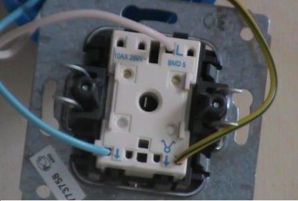
Typically, the letter L indicates the location where the input of the phase wire is connected, and the arrows on the opposite side indicate the location where the wires responsible for the operation of a separate key are connected.
The core, which is most often covered with white insulation, must be connected to the phase input, and the remaining two wires, which are blue and yellow-green in the photo, to the corresponding sockets. After all contacts are connected, you need to unfold the device and install it in the socket box.
In models with self-clamping contacts, connection is extremely simple. The stripped edge of the wire just needs to be inserted into the connection point. There is a clamp installed there that automatically secures the connection with a spring. All three wires are connected in this way.
You need to carefully monitor the color marking of individual cores. Once they are inserted into the connectors, you need to pull back a little to make sure that the connection is secure.If it is necessary to remove the fixed conductors from the clamping contacts, then the connection must be disconnected.
For this purpose, buttons are provided next to each clamp; they can be located at the ends of the device. When you press the button, the clamp opens and the wire can be easily removed. On switches with screw contact retainers, there is often no marking of input and output for wires.
Usually there is a phase input at the top, and two outputs at the bottom. The design of such devices includes a plate to which movable output contacts are attached; their purpose is obvious. To fix the contacts in such a device, you need to unscrew the clamping screw, insert the stripped edge of the wire into the hole, and then screw the fastener back.

In this case, you need to make sure that the edge of the insulation does not end up in the clamping area. Two more screws in such devices are used to fix the presser spacer legs. They are unscrewed to complete the installation of the switch in the socket box. Now you can start connecting the lamps.
Stage #5 - completion of installation work
You need to take a wire of suitable length and lay it in the prepared channel or on the wall/ceiling in accordance with the markings. You need to strip the core and connect it to the desired contact. If you use a standard plastic terminal block, then it is enough to strip 5 mm of wire.
Power is supplied to the second lamp in the same way. Ground wires not used here must be insulated.Now you should take the supply wire that will connect the junction box and the wire coming from the junction box to the switch. The ends of these wires should be freed from external insulation.


The veins are stripped to approximately 40 mm. After this, you need to twist the two phase wires together. It is recommended to make movements clockwise.
Twisting can be done by hand at first, but then you need to strengthen the connection using pliers. Only 5-7 turns of twist should be left, the excess is removed with wire cutters.
This method of connecting electrical communications is considered obsolete and is even prohibited in PUE clause 2.1.21.
Professionals recommend using the following methods for installing electrical wires:
- soldering;
- welding;
- crimping;
- compression connections (screws, clamps, etc.)
We looked at the features of popular and reliable methods of connecting wires in the next article.
If the grounding conductor is not used at this stage, it is recommended to take care of its insulation again. Now you need to clean the end of the phase wire leading to the lamp from the outer and inner covering. It needs to be connected to one of the wires that comes out of the switch.
You need to do the same with the phase wire that leads from the second lamp; it is connected to the second core coming out of the switch.
Again, any unused ground wires should be insulated and placed in the distribution box.If grounding is provided, the corresponding wires must be connected in series. It remains to connect the neutral wires: one from the power wire and two more from the lamps. They are simply twisted together.
Stage #6 - checking the functionality of the circuit
Now all that remains is to screw the light bulbs into the lamp sockets and check the operation of the circuit.

First you need to turn on the RCD and the machine. After this, check the operation of each switch key in turn, and then turn both lamps on and off simultaneously.
If everything is done correctly, the lamps will light up and go out in accordance with the position of the switch keys
After this, you need to turn off the protective devices and insulate all connection points and complete the installation of the two-key switch by installing a decorative frame.
Conclusions and useful video on the topic
A visual process for installing a two-key switch can be seen here:
In fact, connecting such a device is not difficult, you just need to understand the order of all operations and comply with safety requirements. It is better and easier to use modern devices and materials, since they are easier to install and are better combined with each other.
Do you want to clarify some unclear points regarding the installation of a switch that we did not cover in sufficient detail in this article? Or would you like to supplement the above material with valuable comments/advice based on personal experience? Please write your questions in the comments block, express your opinion, and add useful recommendations.


My dad taught me to twist wires (make twists) when assembling boxes (he is an electrician, like me, in fact). From my own observations, I can say that correctly done twisting is a guarantee of a good, strong connection. Not everywhere, however, it is needed. However, it is better not to do it in an apartment, and there are various reasons for this. Twisting deforms the wire, making it unsuitable for reusable use (tips). Soldering, welding, crimping and clamping are all good, but each situation has its own way of crimping a wire. Sometimes you can’t do without twisting either. Old electricians will support me, but new ones will probably not understand.
Gennady, can you list the reasons why twisting is NOT necessary in an apartment? The fact that twisting deforms the wire is understandable, but you don’t fiddle with twists in your apartment once a week or once a month? It’s very rare in practice when you need to climb into a distribution box to scatter wires, and at such a frequency, even aluminum wiring will withstand several dozen deformations, lasting 100 years (and copper wiring will be enough for your great-grandchildren).
Good afternoon, Gennady. “They know” “Electrical Installation Rules” how to connect wires correctly. The book was not invented from scratch - life wrote it.When people were struck by electricity, when houses and businesses burned due to wiring, specialists found out the reasons and obliged designers and installers to follow the correct technologies.
The twists caused many fires, which led to the appearance of clause 2.1.21 and several subsequent ones in the “Rules” (attached screenshot).