Wire colors in electrical engineering: standards and marking rules + ways to identify a conductor
To make the work of electricians easier, the production of cable insulation is subject to certain color marking standards.When connecting a multi-core cable, you can identify the core by the color of the polymer sheath and understand which contact it should be connected to.
Different colors of electrical wires, established by GOST provisions, help speed up the installation process and ensure electrical safety. Agree, understanding color coding is useful to every home craftsman.
We suggest you understand the symbols of electrical wiring, learn GOST standards and learn to read the letter codes of wires on diagrams. In addition, we will tell you how to check the compliance of the connected core with its intended purpose using an indicator screwdriver or a multimeter.
The content of the article:
What GOST and PUE say about color marking
The main document on which to rely during production or purchasing cables, is GOST 31947-2012. Before its appearance, there was no uniformity and order in the field of color designation of electrical wiring.
Until now, in old houses you can find wires in the same sheath, the color of which cannot determine what is connected - “phase”, “zero” or “ground”.

The above-mentioned GOST document states that the insulation of cable products should differ in color. A certain shade should cover the wire with a continuous layer - from beginning to end.It is impossible for one wire at the beginning of the bay to be blue and the end to be white; Intermittent painting is also prohibited.

The regulatory documents also contain recommendations for the use of various circuits for 3-core, 4-core and 5-core cables.
For example, when producing 3-core cables, the following combinations are welcome:
- brown – blue – green/yellow;
- brown – gray – black.
If the cable consists of 4 cores, then two standard color options are also recommended:
- brown – gray – black – green/yellow;
- brown – gray – black – blue.
The diagrams for a 5-core wire look like this:
- brown – gray – black – green/yellow – blue;
- brown – gray – 2 black – blue.
The blue color indicates the “zero” core.
It is not recommended to use only two colors - red and white.

The color must be applied firmly and be clearly visible.
If you turn to the second important document for electricians - the PUE, then in clause 1.1.29 and clause 1.1.30 you can also find information about the color of the phase-neutral-ground wires. More precisely, the data is not listed there, but there is a reference to GOST R 50462-92, which has long been replaced by a more recent edition of GOST R 50462-2009, which is still in force today.
The material corresponds to the information set out in GOST 31947, but there are some clarifications.For example, wires that perform a dual function must be painted in a special way: if the zero worker is combined with the zero protective wire, then it is painted blue along its entire length and has green-yellow stripes along the edges.

Thus, all colors, with the exception of blue (cyan) and green/yellow, can be used to color the insulation of the phase conductor. This group includes white and red colors, which for some reason are not recommended for use by the 2012 edition of GOST.

In Appendix A to GOST R 50462 there is a table in which you can find the letter designations of all colors. For example, the phase conductor of a 1-phase circuit (L) is painted brown, the color code is BN. Letter codes are used for black and white copies of diagrams that do not use different colors.
Core marking for electrical installation solutions
It is not for nothing that at the beginning of the article the idea was voiced that the color designation of conductors greatly simplifies the installation process.
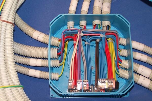
If you are studying on your own electrical wiring in the apartment or private house, select wires in accordance with the standards, when connecting electrical devices, installing automatic protection, distributing wires in junction boxes, you do not need to double-check where the phase, neutral, and ground are - the color of the insulation will tell you about this.
A few examples of electrical installations where marking is important:
There are cables with a large number of cores, the painting of which is not practical. An example is SIP, which uses a different method for identifying conductors. One of them is marked with a small groove along its entire length. The relief core usually performs the function of a neutral conductor, the rest play the role of linear ones.
To distinguish the cores, they are marked with tape, heat shrink, and letter designations, which are applied with multi-colored markers. And in the process of electrical installation work, a ringing is required - additional identification.
Checking the correct connection
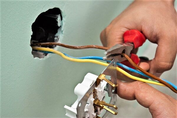
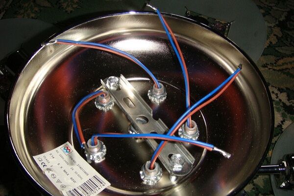
Unfortunately, not all electricians strictly follow the standards and make mistakes in choosing a conductor when making connections. Therefore, when hanging a chandelier, installing a socket or other electrical installation device, it is better to additionally check whether the insulation of each core corresponds to its purpose.

For identification, installers use two methods: the first is checking with an indicator screwdriver, the second is using a tester or multimeter. The phase is usually determined with a screwdriver, and neutral and zero are determined with measuring instruments.
How to use the indicator?
Even such simple devices as indicator screwdrivers are different. Some of them are equipped with a small button, others are triggered automatically when a metal rod and a current-carrying conductor or contact are connected.
But all models without exception have a built-in LED that lights up under voltage.

A screwdriver is a convenient tool for identifying phase conductors. To find out whether the wire is working, use the metal blade of a screwdriver to carefully touch the exposed wire.
If the LED lights up, the wire is energized. The absence of a signal indicates that it is ground or zero.

The verification procedure is performed with one hand, therefore, the other is free. It is better to also use it - for example, to fix wires.But it is strictly forbidden to touch the exposed parts of conductors or metal objects located nearby (pipes, fittings) with your second hand.
Rules for using the tester
An electrician's kit always includes a tester or multimeter. He has to work with the connection of conductors in electrical installations indoors and when assembling the electrical panel. If the wiring was installed a long time ago, marking the wires by color can be neglected.
Even if the insulation colors seem to be consistent, it is not a fact that they are connected according to all the rules.

Before taking measurements, you should study the instructions that accompany all measuring instruments.
The procedure is approximately as follows:
- we set a value that is obviously higher than the expected voltage, for example, 260 V;
- connect the probes to the required sockets;
- we touch two conductors with probes - presumably phase and neutral;
- repeat the procedure with another pair of conductors.
The combination of phase-zero cores should produce a result close to 220 V. It will always be higher than the phase-ground pair.
There are both digital, modern instruments on sale, as well as outdated ones, with arrows and value scales. It is more convenient to use digital ones. Before installing electrical devices yourself, we recommend learning how to use either an indicator screwdriver or a multimeter - you should not rely only on the color of the wires.
The ability to use a multimeter will be useful for a home handyman to check the voltage in an outlet.Detailed instructions for using the tester are given in this article.
Conclusions and useful video on the topic
Generally accepted color coding standards:
Marking methods in addition to color:
When all the wires are the same color - check with a test lamp:
Color coding of cores is a great way to identify wires during installation. However, when working with already installed cables, you should not rely only on the appearance of the conductors, as they may be connected incorrectly.
You should definitely use additional methods for identifying the wires, and if the wires themselves cannot be changed, then you need to mark them with colored tape or letter symbols.
Do you have anything to add or have questions about color coding? You can leave comments on the publication, participate in discussions and share your own experience in identifying conductors. The contact form is located in the lower block.


The indicator screwdriver is easy to use, but you need to be careful with it. Most of them are designed to operate with a voltage of 220 volts, but sometimes a voltage of 380 volts is supplied to the house. In this case, the screwdriver may miss the charge and you will receive an electric shock. And there are a lot of counterfeit products on the market now. You should choose carefully and purchase the indicator in trusted stores.
Good afternoon, Anton.
I fully support your warnings regarding the purchase and use of voltage indicators.
I want to emphasize that professional electric power industry uses equipment, instruments, and indicators, which are divided into categories: “up to 1000 volts” and “over 1000 volts.”For the home, of course, you need to purchase indicators of the first category.
From your comment it follows that you have started working on home electrical networks. To improve your skills and obtain useful information to insure against electrical injury, I advise you to read “Rules for the construction of electrical installations”, “Safety rules for the operation of electrical installations”.
Let me add: the “correct” voltage indicator has a Certificate that limits the scope of application of the device. The screenshot shows part of such a Passport for the E119.2 indicator.