Terminals for connecting wires: which terminal blocks are better and how to work with them
Maintenance of electrical networks inevitably involves work with terminals for electricians.This is a kind of small mounting hardware, the use of which is difficult to do without when connecting wires to each other or to electrical equipment.
Time has eliminated outdated terminals for connecting wires from practice, but is steadily supplementing the base of electrical engineering with new developments - more advanced ones.
We will help you understand the variety of electrical accessories. The article discusses different types of terminal blocks and describes their application and installation features.
The content of the article:
Types of electrical connections with terminal block
Considering all the terminals produced by the industry for connecting wires, you should immediately make a reservation and divide the products into two types: electrical and electrical.
In fact, the difference (in current load) between the types is often small, but it still exists. This point should be kept in mind when selecting electrical terminals for installation, repair or other actions.
Faced with necessity selection of electrical terminals for wires, it is better to start with the simplest designs of domestic production - reliable, durable, proven in practice more than once.
The following types of “clamps” are distinguished:
- knife;
- ring;
- pin;
- coupling
Connections when constructing electrical circuits can be made using different methods, and terminals are just one of the options. However, this option seems to be the simplest, most convenient and even economical compared to, for example, soldering and welding, including cold welding.
Option #1 - “sheath”
These are perhaps the most common design options for products. They can often be found as part of the electrical circuits of many household appliances: irons, refrigerators, heating devices, etc.
But for conductor connections power electrical wiring, for example, in residential electrical panels, they are not intended.
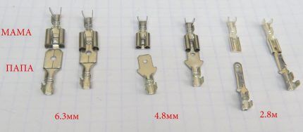
It is permissible to install this type of electrical products on conductors (multi-core) with a cross-section of 0.26 - 6.0 mm by force crimping the shank.
There are two types of such products: insulated and non-insulated. The insulation is usually painted in different colors (red, blue, yellow) depending on the rated power of the terminal block. Products are used in pairs in a “father-mother” combination.
Option #2 - ring
Ring products are configured for screw fastening and are presented in two groups. Both groups are classified as non-insulated terminals.
The first group includes designs of a closed ring with a shank. The second group consists of fork-type structures with a break in the contour of the ring, also with a shank. Both are widely used in electronic circuits.
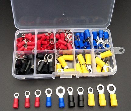
Ring terminal blocks of the first type are available in a wider range than the second type. And the possibilities for their use are more extensive, taking into account the technical characteristics.
This type of electrical products can be installed on electrical conductors with a cross section of 0.25 - 16.8 mm. And the fork configuration of the connecting terminals for wires is designed only for wire cross-sections of 0.25 - 4.6 mm.
Option #3 - pin
This group of connecting terminals for electrical wires is made according to the principle of a detachable part, consisting of two separate elements - a plug and a socket.
The plug is marked with the symbol “A”, for example, F2A. The socket is marked with the symbol “B”, for example, F2B. Mounting on conductors with a cross-section of 1.25 – 6.64 mm is supported. The main purpose of pin terminals is to ensure the connection of electrical conductors.
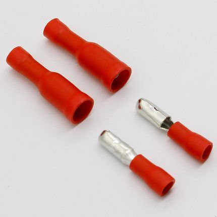
This group of mounting accessories refers to insulated products. The tail part of the terminals is covered with insulating material. Depending on the design power of the terminal block for connecting the wires, the insulator is colored accordingly.
Insulators of electrical terminals for conductors with a cross section of up to 2 mm are painted blue, the rest (from 2 to 6.64 mm) are painted yellow.
Option #4 - coupling clamps
Another type of connecting fittings is a coupling contact clamp, made in the form of a metal tube.
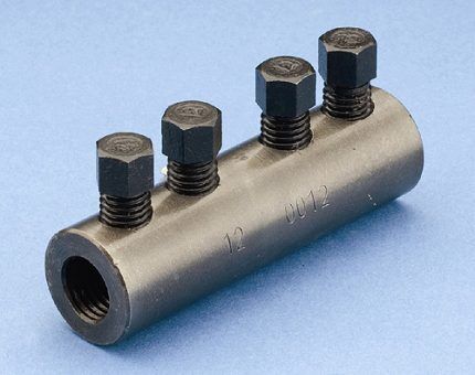
The couplings are designed for installation on electrical conductors with a cross-section of 0.25 – 16.78 mm.
Fixation is carried out by forcefully crimping part of the tube or using bolts screwed into threaded holes on the coupling body. As a rule, crimp couplings are not used for connecting single-core wires.
Foreign products
In recent years, the market has been filled with foreign-made terminal blocks. We must pay tribute: technologically, foreign designs look more advanced compared to domestic products. It is more convenient to work with them - it is faster and easier to make connections.
But from the point of view of the reliability of connections made by a foreign product, not everything is so simple. In this regard, a domestic product often looks preferable. However, let's look at some examples.
Electrical ones are noteworthy company terminals WAGO. The company's engineers have invented several attractive designs, where an ordinary terminal turns into a convenient interface for connection: Push wire, Power cage clamp, Cage clamp.
Connector #1 - Push Wire
Technology Push Wire is based on the use of the rigidity properties of the electrical conductor, due to which a completely reliable contact is obtained.
This type of terminal block is most suitable for working with single-core wire. Indeed, Push Wire provides a fast connection method without any reservations.
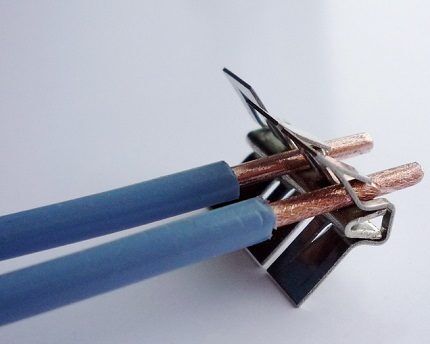
It's enough just strip part of the wire (by 10-15 mm) and with a slight force push the stripped end into the terminal.And in order to remove the conductor just as quickly, it needs to be pulled out while simultaneously scrolling around its axis.
Two types of Push Wire connectors have been developed:
- Under a single conductor.
- Under a group of conductors.
The group connection configuration is designed to work with wires of lower rigidity than in the case of a single connection. A slightly different mechanical clamp design is used here.
To gain access to the conductor entry holes, some force must be applied to the push button. There are also Push wire models without a button - under the pressure action of a screwdriver.
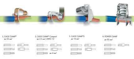
Connector #2 – universal Power cage clamp
This terminal block belongs to the category of universal designs. It is made for any type of electrical wire with a cross-section of 6 – 95 mm.
Structurally Power cage clamp is a so-called double cage, where there is a spring press and a current-carrying busbar.
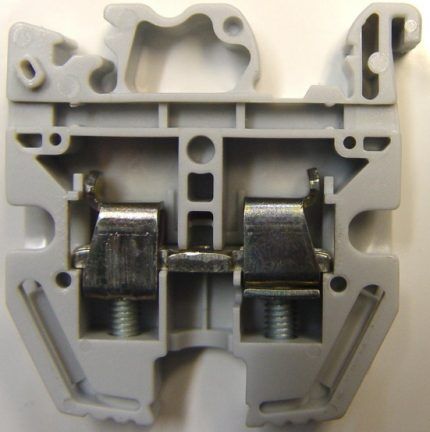
Connecting electrical conductors to such terminals is done using a hex key. By rotating the key, the spring is pressed, the end of the wire is inserted under the press, then the key is turned counterclockwise. As a result, the press lowers and reliably presses the inserted end of the wire.
Connector #3 – stacked Cage clamp
This is a unique, patented WAGO, a product that has received the characteristics of a wire terminal block.WAGO pre-assembled terminal blocks are designed for installation on wires with a cross-section of 0.5 – 35 mm.
They are well suited not only for working with single-core wires, but also with multi-core wires, regardless of the degree of thinness of the individual wires.
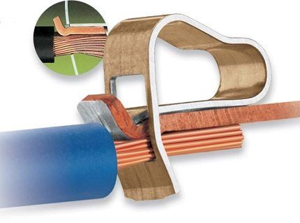
Valid Cage clamp simple: using a screwdriver (or a special lever in other modifications), lift the spring clamp, insert the wire under the current-carrying busbar, and then lower the clamp into place. This product is a type self-clamping terminal blocks.
Despite the simplicity of the design, the manufacturer claims: the clamping force on the contact is adjusted automatically and directly depends on the cross-section of the wire.
Connector #4 - Cage clamp S
Wire connector option, almost identical to the product described above. But the design Cage clamp S still somewhat different. The peculiarity of the “S” modification is the ability to work with a terminal of this type without the use of any electrician’s tools.
Plus, the terminal block of modification “S” is designed for conductors of sufficiently high rigidity - stranded and single-core. It is also permissible to connect wires with metal tips to the terminal.
Working with Cage clamp S is very simple: the end (stripped) part of the conductor is inserted with some force until it stops, after which the connection is established.
Connecting terminals for wires from the Cage clamp S series have found a place in almost all modifications of group multi-row terminal blocks.
They are convenient to use for the installation of numerous low-current electrical lines. However, the closed design of the Cage clamp S is also successfully used in high current circuits.
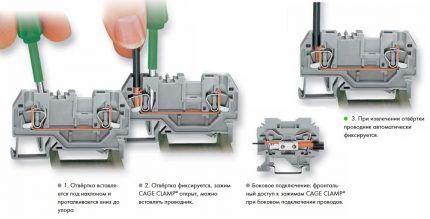
There are two modifications of the fully insulated “S” design. One involves securing the wire while pressing the plate in the frontal direction. The other is designed to perform side pressure with a screwdriver on a springy plate.
Screw wire connectors
Screw connectors are widely used in the electrical industry; in fact, they are a variation of a tubular (coupling) product. They are made in the form of a rectangular tube, but with a rounded (oval) bottom.
On the upper plateau of such a tube there are threaded holes into which locking screws are screwed. The entire structure is enclosed in nylon insulation. For access to the screws, passage channels are made in the insulation body. There are two types of such terminal blocks for connecting wires - single and group.
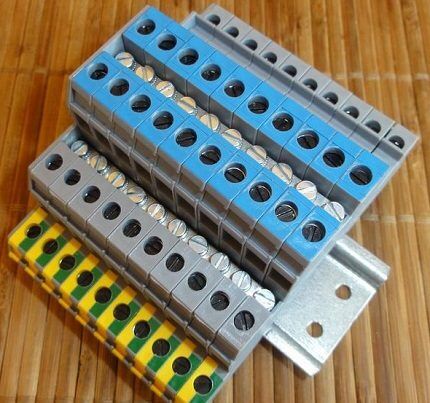
Screw terminal blocks for connecting wires have:
- pronounced mechanical strength;
- ability to work with cables with a cross-section of up to 25 mm;
- use in low current and power circuits.
Working with this type of connectors is easy.
The end parts of the wires are inserted inside the brass tube and the locking screws (usually two screws) are tightened with a screwdriver. In turn, the screws press the conductor to the bottom of the metal tube.
In addition to terminals, there are alternative methods for connecting wires. For more information on using terminal strips and other solderless methods, see this article.
Conclusions and useful video on the topic
The presented video material will expand your knowledge about the types of terminals and methods of their installation.
Electrical installation work is rarely complete without the use of the described accessories. It would seem that these are small details that are easy to discard, replacing the technological connection with the usual twisting of wires.
But The practice of electrical engineering is marked by a lot of cases when it is the banal twisting of conductors instead of a reliable terminal connection that leads to tragic consequences.
Do you have experience using terminals to connect wires? Or still have questions on the topic? Please share your opinion and leave comments. The communication block is located below.


I'm not an expert; I haven't even seen most of the terminals shown here. And in general, it is not entirely clear why they are described. The title is “which terminal blocks are better and how to work with them,” but there’s only a little about the terminal blocks in the video. I think the topic is completely unsolved. The topic is interesting and relevant. Pros, cons, in what situations which one and why, price. It would be nice to read.
Good day, Sergey.
After your comment I re-read the article. Your conclusion is unfounded - the very first section states: it is better to choose domestic ones.The following is an explanation: tested by operation, reliable, durable.
When describing the terminals, the author relates the type of product to the situation - these are used in irons, coffee makers, they can be found in electronics, etc.
A separate section is devoted to foreign products. Here the author emphasizes: they look more perfect than domestic ones, are easier to install, but...then follow the conclusions that, judging by your review, were not enough.
Prices, I agree, are not, but today’s pegging of the ruble to the dollar forces manufacturers to systematically adjust the cost of the product.
Attached is a screenshot with key points.
I am also an engineer and I agree with Sergei.
In our time, terminal blocks were simply called: twisting, soldered or not, on top of electrical tape. Now your eyes are wide open, you don’t know which one to use where. Screw connectors were the first to appear: very convenient, you can cut so many wires, so many tubes. There are through holes for mounting to the panel. In old apartments, in distribution boxes, the twists were insulated with caps like ballpoint pens. Based on them, connectors were made that were screwed onto a group of wires. They hold up well. They are of different sizes, so they are suitable for any cross-section. Typically, terminal blocks are used for detachable connections of boards, motors, etc.
A normal article for someone who generally understands what we are talking about. Even from the pictures you can choose the desired connection method in a particular case. And non-specialists need to start not with Arduino kits, but with Ohm’s law and have an amateur radio talent to do this. Good luck everyone, thanks for the article!!!