Connection diagram for water heated floor: design options and device manual
Warm water-type floors are becoming increasingly popular among owners of private houses heated by a boiler.A combined system, equipped in accordance with all the rules, works properly for 15-20 years. A well-chosen connection diagram for a water heated floor (WHP) ensures the supply of coolant, heating it to the desired temperature and distribution along the circuits.
In this article we will analyze in detail the assembly features of the collector unit and the system connection diagram. We also provide detailed installation instructions. But first, let’s look at when a water floor becomes useful and when it is inappropriate to install it.
The content of the article:
Restrictions for installation of high-voltage transformer
Manufacturers of components for underfloor heating (HF) do not always specify whether there are restrictions for installing water systems, but they exist. In some cases, it is prohibited to install heating structures.
Where it is not customary to install water floors:
- In multi-apartment buildings. Central heating is distributed between apartments. An additional connection in one of them will lead to heating and hydraulic imbalance.
- In public places. Floor heating is considered ineffective, since heat loss is high, and essentially economical systems become expensive during operation.
- In residential premises with insufficient thermal insulation as the main source of heat. One of the conditions for installing heated floors in the northern regions is to reduce heat loss due to wall insulation and floors, as well as installation of radiators around the perimeter of the premises, under the windows.
The most effective heating system is considered to be a combination of traditional radiator heating with heated floors, with radiators remaining the main sources of heat.
But sometimes the system hidden under the flooring plays a major role:
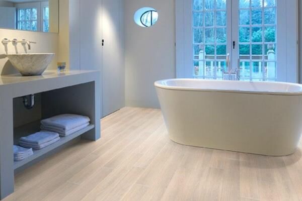
Warm floors, equipped in compliance with standards and technological nuances, are safe, hygienic and do not affect the aesthetics of the premises.
And the selected connection diagram is responsible for the functionality and ease of use, which we will describe in more detail.
Analysis of the connection diagram with the collector
There are several options for designing a water TP system. But the design with collector – a multifunctional unit that distributes coolant.
Heating operating principle
The main source of heat supply in the house, as a rule, is an autonomous generator, the function of which is usually performed by a boiler. The type of boiler does not matter, but it is estimated that gas costs 6-7 times less than electric.

The temperature of heating water reaches 95 °C. The system is closed, and the return temperature is lower - approximately 65-70 °C. But these parameters are not suitable for heated floors; the maximum permissible value is 55 °C. In practice, the coolant enters the HTP pipes even cooler - 35-45 °C.
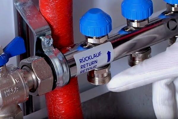
To adjust the desired temperature, a return line is connected to the circuits and installed mixing unit, which performs stream mixing.

The temperature in the system can be adjusted manually, based on data from temperature sensors. However, there are gas boilers designed for direct connection of the VTP. They automatically supply water at a preset temperature of 40-45 °C.
Solid fuel boilers are difficult to regulate. In order for the coolant in a system with a solid fuel generator to reach the normal level, an additional buffer tank must be installed.
And here electric boilers are ideal, since the desired temperature is maintained automatically, however, this is the most expensive heating method and not economically profitable.
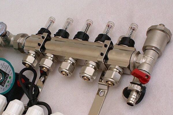
Selection and assembly of the collector assembly
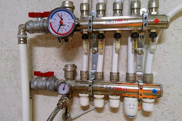
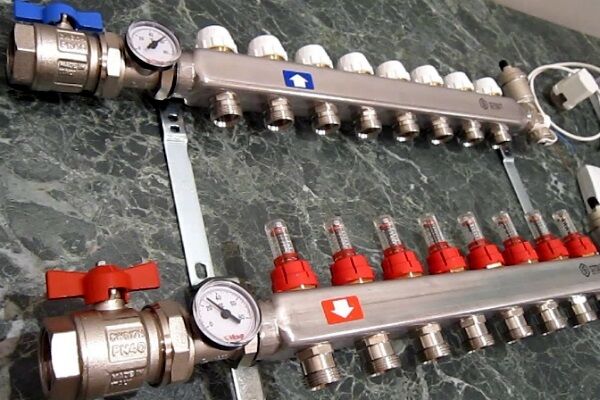
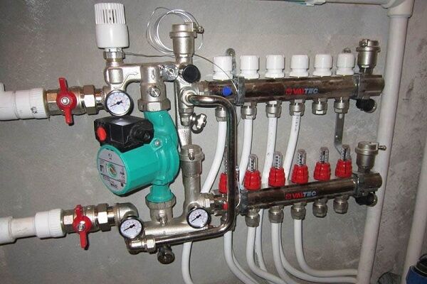
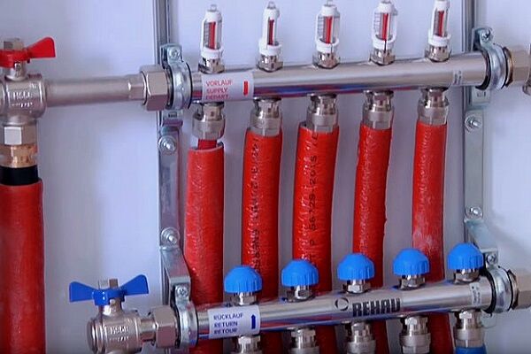
The HTP circuits are connected to the heating system through a distribution manifold.This is a unit that allows you to adjust the coolant supply, control temperature and flow, balance circuits, and remove air from the system. Separate elements are responsible for each function: pump, flow meters, pressure gauge, thermostats.

To select the right components for assembling a mixing and manifold assembly, it is better to hire a specialist who is well versed in the quality of the parts on the market.
Main elements of the node:
In addition to the listed components, you will need fittings (axial, compression or press fittings), and special brackets. The entire unit is usually placed in a manifold cabinet, which can have different designs and installation locations.
Step-by-step installation instructions
The water floor is connected to the heating system at the final stage, when the construction work has been completed and the manifold cabinet has been assembled and installed.
The entire installation process of the ETP system includes the following steps:
- Design, calculations, drawing up a diagram.
- Preparing the base installation of insulation;
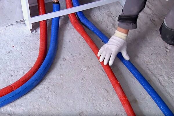
- Correct laying and fastening of pipes, reinforcing mesh;
- Filling circuits with coolant, hydraulic tests.
- Fill screeds, laying the final floor covering.
- Connection to the system, balancing of circuits.
- Commissioning, testing.
As you can see, connection activities are performed at the very end. And here balancing of circuits plays an important role. Each loop has a different length; accordingly, all circuits differ in hydraulic resistance.
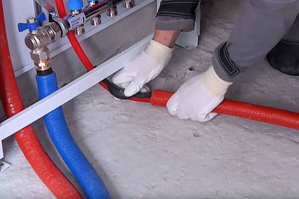
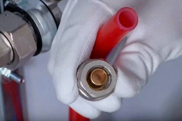
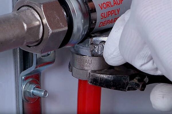
Instructions for connecting pipes:
If you install a manifold assembly without flow meters, the heating function will be impaired. When the system is put into operation, the coolant will tend to enter smaller circuits with minimal resistance. As a result, rooms with short circuits will be heated according to the design, while rooms with long circuits will remain unheated.
Balancing should begin when the manifold is connected to the supply and return pipes.

Balancing instructions:
- Open the supply and return valves alternately. Make sure that the air vents are also open.
- When the boiler is off, turn on the circulation pump and set the thermostat to the maximum temperature.
- Bring the pressure in the system to normal – 1-3 bars.
- Close valves on all circuits, leave only the longest one. Record flow meter data.
- Open the valve on the second longest loop. Adjust the flow rate to the first result using a balancing valve.
- Continue to open the valves on the circuits one by one, from long to short, adjusting the flow rate to one value (the first).
Using convenient functionality, you can always adjust the flow parameters. But everything will have to be done manually, focusing on the value in the longest contour.
It is prohibited to start operation at full power at once; the temperature of the coolant in the system should be raised gradually. On the first day, water is supplied slightly above room temperature - +25 °C, then 5-6 °C is added every day. The desired temperature is set on the thermostat.

It is not necessary to increase the pump speed; it is better if it works at the first one. The normal temperature difference between supply and return is 5-10 °C, but if the value is higher, then the pump speed can be increased.
Connection diagram from the heating radiator
Sometimes, instead of the “boiler - mixing-collector unit - circuits” diagram, other options for connecting a heated floor are used. And the most common of them is connecting the ETP circuit to a heating radiator.
The diagram looks like this:

The disadvantage of the scheme is the seasonal use of heated floors. As you know, heating radiators are not used in the summer, therefore, the floor will also remain cold.
To prevent the coolant temperature from rising above normal, a special sensor with a valve is included in the circuit. It automatically shuts off the flow of water as soon as it becomes too hot. When the coolant has cooled to an acceptable temperature, thermal valve opens again.
This type of VTP can be organized without a pumping and mixing unit. The only adjustment tool is a thermostatic device installed on the supply pipe.
Conclusions and useful video on the topic
Overview of connection methods:
Option for connecting a circuit without a collector:
How to assemble a pumping and mixing unit
When choosing a diagram for connecting an HTP to a heating system, it is better to consult with a specialist in order to take into account all the nuances of further operation.
If you do not have the skills to assemble a collector-mixing unit yourself, we recommend buying a ready-made one.
Do you use a heated floor that you assembled and connected yourself and want to share useful installation tips and warn beginners about possible mistakes? Write your comments in the block below, add photos and recommendations.
Maybe you have questions about the topic of the article? Feel free to ask our experts below this material.


Warm floors are a cool thing, my relatives installed one and couldn’t be happier.Their cat is especially happy, as he can now warm his belly by simply lying on the floor. Moreover, the first floor of their house is heated exclusively with warm water floors. Their floors are covered with regular laminate. They did all this, of course, not on their own, but hired craftsmen. I, too, would not dare to make a warm water floor myself, it is not easy and fraught with mistakes, and the whole thing is not cheap.
Do I need to obtain any permits to install a warm water floor in a Khrushchev-era building? We plan to make the third floor from central heating.
We have to disappoint you: the fact is that panel houses that were built from the 1950s to the 1980s are simply not functionally suitable for laying water-heated floor pipes.
This is due to a number of reasons:
— low ceiling height (“pie” of a warm water floor 10+ cm);
— the possibility of installing the boiler is difficult;
— the central heating system is not designed for such projects.
All this leads to the fact that you will receive a high starting cost for equipment and installation.
For Khrushchev it would be more practical to implement a heated floor based on a heating film. This is explained by the fact that heating from IR film does not require a cement screed; the elements can be laid directly under the floor covering itself. But before installing a heated floor from IR film, make sure that the apartment’s wiring is designed for such loads.
Hello. Yes, of course, since installing a warm water floor will create additional load on the system. The first thing you need to do is go to the Criminal Code and they will tell you everything. However, for example, in Moscow there is a clause.11.8 Appendix 1 of PPM 508-PP, which prohibits such structures. It is necessary to clarify at the regional level whether there are such prohibitions in your city.