How to calculate a heated floor using a water system as an example
The effectiveness of underfloor heating is influenced by many factors.Without taking them into account, even if the system is correctly installed and the most modern materials are used for its construction, the actual thermal efficiency will not live up to expectations.
For this reason, installation work must be preceded by a competent calculation of the heated floor, and only then can a good result be guaranteed.
Developing a heating system project is not cheap, so many home craftsmen carry out the calculations on their own. Agree, the idea of reducing the cost of installing heated floors seems very tempting.
We will tell you how to create a project, what criteria to consider when choosing the parameters of a heating system, and describe a step-by-step calculation method. For clarity, we have prepared an example of calculating a heated floor.
The content of the article:
Initial data for calculation
Initially, a properly planned course of design and installation work will eliminate surprises and unpleasant problems in the future.
When calculating a heated floor, you must proceed from the following data:
- wall material and design features;
- dimensions of the room in plan;
- type of finishing coating;
- designs of doors, windows and their placement;
- arrangement of structural elements in plan.
To carry out competent design, it is necessary to take into account the established temperature regime and the possibility of its adjustment.

There are recommendations regarding the floor temperature that ensures a comfortable stay in rooms for various purposes:
- 29°С - living sector;
- 33°С- bath, rooms with a swimming pool and others with high humidity;
- 35°C — cold zones (at entrance doors, external walls, etc.).
Exceeding these values entails overheating of both the system itself and the finishing coating, followed by inevitable damage to the material.
Having carried out preliminary calculations, you can choose the optimal temperature of the coolant according to your personal feelings, determine the load on the heating circuit and purchase pumping equipment that perfectly copes with stimulating the movement of the coolant. It is selected with a margin of 20% coolant flow.

At the design stage, you should decide whether the heated floor will be the main supplier of heat or will be used only as an addition to the radiator heating branch. The share of thermal energy losses that it has to compensate for depends on this. It can range from 30% to 60% with variations.
The heating time of the water floor depends on the thickness of the elements included in the screed. Water as a coolant is very effective, but the system itself is difficult to install.
Determining the parameters of a heated floor
The purpose of the calculation is to obtain the value of the thermal load. The result of this calculation influences the subsequent steps taken. In turn, the heat load is affected by the average winter temperature in a particular region, the expected temperature inside the rooms, and the heat transfer coefficient of the ceiling, walls, windows and doors.

The final result of the calculations before underfloor heating device water type will also depend on the presence of additional heating devices, including the heat emission of people living in the house and pets. The presence of infiltration must be taken into account in the calculation.
One of the important parameters is the configuration of the rooms, so you will need a floor plan of the house and corresponding sections.
Method for calculating heat loss
Having determined this parameter, you will find out how much heat the floor should generate for the comfortable well-being of the people in the room, and you will be able to select the boiler, pump and floor according to power. In other words: the heat given off by the heating circuits must compensate for the heat loss of the building.
The relationship between these two parameters is expressed by the formula:
MP = 1.2 x Q, Where
- MP - required circuit power;
- Q - heat loss.
To determine the second indicator, measurements and calculations of the area of windows, doors, ceilings, and external walls are taken. Since the floor will be heated, the area of this enclosing structure is not taken into account. Measurements are taken on the outside, including the corners of the building.
The calculation will take into account both the thickness and thermal conductivity of each structure. Standard values thermal conductivity coefficient (λ) for the most commonly used materials can be taken from the table.

Heat loss is calculated separately for each building element using the formula:
Q = 1/R*(tв-tн)*S x (1+∑b), Where
- R — thermal resistance of the material from which the enclosing structure is made;
- S — area of the structural element;
- tв and tн — internal and external temperatures, respectively, with the second indicator taken according to the lowest value;
- b — additional heat losses associated with the orientation of the building relative to the cardinal directions.
The thermal resistance index (R) is found by dividing the thickness of the structure by the thermal conductivity coefficient of the material from which it is made.
The value of coefficient b depends on the orientation of the house:
- 0,1 - north, northwest or northeast;
- 0,05 - west, southeast;
- 0 - south, southwest.
If we consider the question using any example of calculating a water-heated floor, it becomes clearer.
Specific calculation example
Let’s say the walls of a house for non-permanent residence, 20 cm thick, are made of aerated concrete blocks. The total area of the enclosing walls excluding window and door openings is 60 m². External temperature -25°С, internal +20°С, design is oriented to the southeast.
Considering that the thermal conductivity coefficient of the blocks is λ = 0.3 W/(m°*C), it is possible to calculate the heat loss through the walls: R=0.2/0.3= 0.67 m²°C/W.
Heat losses are also observed through the plaster layer. If its thickness is 20 mm, then Rpcs. = 0.02/0.3 = 0.07 m²°C/W. The sum of these two indicators will give the value of heat loss through the walls: 0.67+0.07 = 0.74 m²°C/W.
Having all the initial data, we substitute them into the formula and get the heat loss of a room with the following walls: Q = 1/0.74*(20 - (-25)) *60*(1+0.05) = 3831.08 W.
In the same way, heat loss through other enclosing structures is calculated: windows, doorways, roofing.

To determine heat loss through the ceiling, its thermal resistance is taken equal to the value for the planned or existing type of insulation: R = 0.18/0.041 = 4.39 m²°C / W.
The ceiling area is identical to the floor area and is equal to 70 m². Substituting these values into the formula, the heat loss through the upper building envelope is obtained: Q sweat. = 1/4.39*(20 - (-25))* 70* (1+0.05) = 753.42 W.
To determine heat loss through the surface of windows, you need to calculate their area. If there are 4 windows 1.5 m wide and 1.4 m high, their total area will be: 4 * 1.5 * 1.4 = 8.4 m².
If the manufacturer indicates separately the thermal resistance for the glass unit and the profile - 0.5 and 0.56 m²°C/W, respectively, then Rocon = 0.5*90+0.56*10)/100 = 0.56 m²°C/ Tue Here 90 and 10 are the share per each element of the window.
Based on the data obtained, further calculations continue: Qwindow = 1/0.56*(20 - (-25))*8.4*(1+0.05) = 708.75 W.
The outer door has an area of 0.95 * 2.04 = 1.938 m². Then Rdv. = 0.06/0.14 = 0.43 m²°C/W. Q door = 1/0.43*(20 - (-25))* 1.938*(1+0.05) = 212.95 W.

As a result, the heat loss will be: Q = 3831.08 +753.42 + 708.75 + 212.95 + 7406.25 = W.
To this result add another 10% for air infiltration, then Q = 7406.25 + 740.6 = 8146.85 W.
Now you can determine the thermal power of the floor: Mp = 1.*8146.85 = 9776.22 W or 9.8 kW.
Required heat to heat the air
If the house equipped with a ventilation system, then some part of the heat released by the source must be spent on heating the air coming from outside.
The formula is used for calculation:
Qv. = c*m*(tв—tн), Where
- c = 0.28 kg⁰С and denotes the heat capacity of the air mass;
- m The symbol indicates the mass flow of outside air in kg.
The last parameter is obtained by multiplying the total volume of air, equal to the volume of all rooms, provided that the air is renewed every hour, by the density, which varies depending on the temperature.

If the building receives 400 m3/h, then m=400*1.422 = 568.8 kg/h. Qv. = 0.28*568.8*45 = 7166.88 W.
In this case, the required thermal power of the floor will increase significantly.
Calculation of the required number of pipes
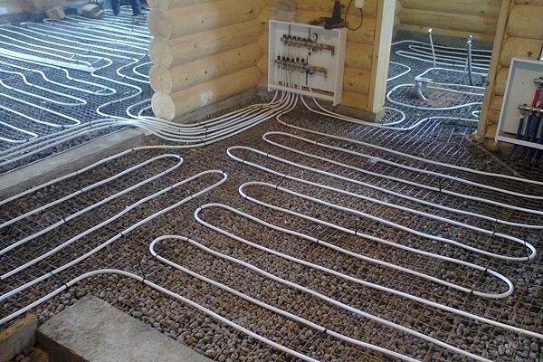
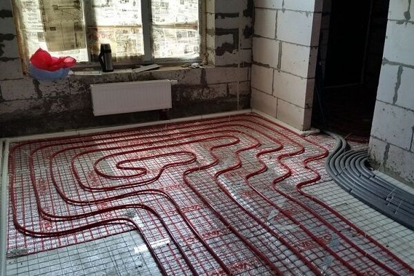
For installing a water-heated floor, choose different pipe laying methods, differing in shape: three types of snake - the actual snake, angular, double and snail. In one mounted circuit there can be a combination of different shapes. Sometimes a “snail” is chosen for the central area of the floor, and one of the types of “snake” is chosen for the edges.

The distance between the pipes is called the pitch. When choosing this option, you need to satisfy two requirements: your foot should not feel the temperature difference in individual areas of the floor, and you need to use the pipes as efficiently as possible.
For border zones of the floor, it is recommended to use a step of 100 mm. In other areas, you can choose a pitch ranging from 150 to 300 mm.

To calculate the length of the pipe there is a simple formula:
L = S/N*1.1, Where
- S — contour area;
- N — laying step;
- 1,1 — margin for bending 10%.
To the final value is added a section of pipe laid from the collector to the distribution of the warm circuit both on the return and supply.
Calculation example.
Initial values:
- square — 10 m²;
- distance to collector — 6 m;
- laying step - 0.15 m.
The solution to the problem is simple: 10/0.15*1.1+(6*2) = 85.3 m.
When using metal-plastic pipes up to 100 m long, a diameter of 16 or 20 mm is most often chosen. With a pipe length of 120-125 m, its cross-section should be 20 mm².
The single-circuit design is only suitable for rooms with a small area. The floor in large rooms is divided into several contours in a ratio of 1:2 - the length of the structure should be 2 times the width.
The previously calculated value is the extent floor pipes generally. However, to complete the picture, it is necessary to highlight the length of a separate contour.
This parameter is influenced by the hydraulic resistance of the circuit, determined by the diameter of the selected pipes and the volume of water supplied per unit time. If these factors are neglected, the pressure loss will be so large that no pump will force the coolant to circulate.

Contours of the same length are an ideal case, but in practice they are rarely encountered, because the area of rooms for different purposes is very different and it is simply impractical to reduce the length of the contours to one value. Professionals allow a difference in pipe lengths of 30 to 40%.
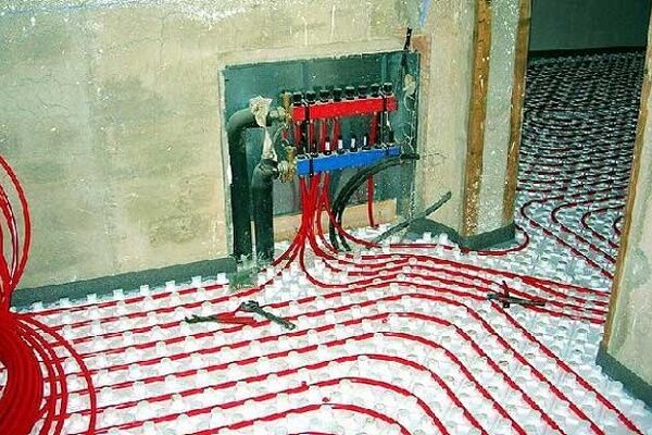
The diameter of the collector and the throughput of the mixing unit determine the permissible number of loops connected to it. In the passport for the mixing unit you can always find the amount of thermal load for which it is designed.
Let's say the throughput coefficient (Kvs) is equal to 2.23 m3/h. With this coefficient, certain pump models can withstand a load of 10 to 15 W.
To determine the number of circuits, you need to calculate the thermal load of each.If the area occupied by a heated floor is 10 m², and the heat transfer is 1 m², then the indicator Kvs is 80 W, then 10*80 = 800 W. This means that the mixing unit will be able to provide 15,000/800 = 18.8 rooms or circuits with an area of 10 m².
These figures are maximum, and they can only be applied theoretically, but in reality the figure needs to be reduced by at least 2, then 18 - 2 = 16 circuits.
Required during selection mixing unit (collector) see if it has such a number of conclusions.
Checking the correct selection of pipe diameters
To check whether the pipe cross-section was selected correctly, you can use the formula:
υ = 4*Q*10ᶾ/n*d²
When the speed corresponds to the found value, the pipe cross-section is selected correctly. Regulatory documents allow a maximum speed of 3 m/sec. with a diameter of up to 0.25 m, but the optimal value is 0.8 m/sec., since as its value increases, the noise effect in the pipeline increases.
Additional information on the calculation of underfloor heating pipes is given in this article.
Calculating the circulation pump
To make the system economical, you need choose a circulation pump, providing the required pressure and optimal water flow in the circuits. Pump passports usually indicate the pressure in the circuit of the longest length and the total coolant flow in all loops.
The pressure is influenced by hydraulic losses:
∆h = L*Q²/k1, Where
- L — contour length;
- Q — water consumption l/sec;
- k1 - coefficient characterizing losses in the system; the indicator can be taken from reference tables on hydraulics or from the equipment passport.
Knowing the magnitude of the pressure, calculate flow rate in system:
Q = k*√H, Where
k is the flow coefficient.Professionals assume the flow rate for every 10 m² of a house is within 0.3-0.4 l/s.

The figures regarding pressure and flow rates indicated in the passport cannot be taken literally - this is the maximum, but in fact they are influenced by the length and geometry of the network. If the pressure is too high, reduce the length of the circuit or increase the diameter of the pipes.
Recommendations for choosing screed thickness
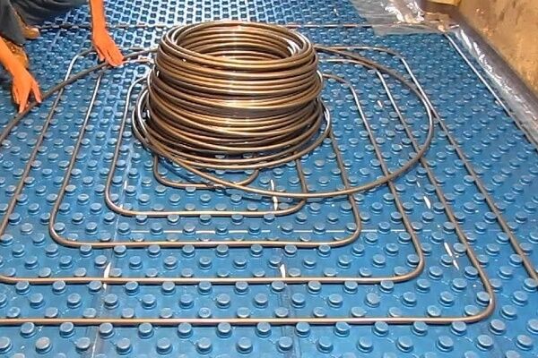
In the reference books you can find information that the minimum thickness of the screed is 30 mm. When the room is quite high, insulation is placed under the screed, which increases the efficiency of using the heat given off by the heating circuit.
The most popular backing material is extruded polystyrene foam. Its heat transfer resistance is significantly lower than that of concrete.
When installing a screed, in order to balance the linear expansion of concrete, the perimeter of the room is decorated with a damper tape. It is important to choose the right thickness. Experts advise that for a room area not exceeding 100 m², install a 5 mm compensating layer.
If the area values are larger due to the length exceeding 10 m, the thickness is calculated using the formula:
b = 0.55*L, Where
L is the length of the room in m.
Conclusions and useful video on the topic
This video is about the calculation and installation of a heated hydraulic floor:
The video provides practical recommendations for laying the floor. The information will help you avoid mistakes that amateurs usually make:
The calculation makes it possible to design a “warm floor” system with optimal performance indicators. It is permissible to install heating using the passport data and recommendations.
It will work, but professionals advise still spending time on calculations so that the system ultimately consumes less energy.
Do you have experience in calculating underfloor heating and preparing a heating circuit design? Or still have questions on the topic? Please share your opinion and leave comments.


I tried to calculate the loss of thermal energy using your method, but it didn’t work out on my own. I studied the information up and down, either I don’t understand anything about this, or you’ve confused everything too much. Is it possible to install underfloor heating not in every room, but only in the nursery and kitchen? Or is the system being developed for the entire square footage of the house? And how do I know which type of pipe installation is right for me: snail or snake?
Hello. Yes, you can not do this in every room. Regarding the second question, please read this article. I quote from there:
“The layout of underfloor heating pipes is carried out according to two main schemes: “snake” or “snail”. “Snail” is preferred. In this case, the pipes through which hot water enters the system are laid parallel to the pipes through which the cooled coolant moves. As a result, part of the heat from hot areas is transferred to the cooled part of the circuit, which ensures more uniform heating of the room.
“Snake” is a sequential pipe laying scheme; it is more suitable for rooms with a small area.Sometimes both layout schemes are used: in large areas - a “snail”, and in small areas, for example, in a short corridor, in a bathroom, a “snake” is used. It also makes sense to clarify the characteristics of the boiler from which the coolant will be supplied.”
A warm floor is a rather useful invention, but for its installation a number of conditions must be met. First of all, it all depends on the region of residence. After all, there is a difference: you live in Siberia or in Crimea. In Siberia, in addition to the floor, you also need to take care of radiators. Also, the calculations take into account the thermal conductivity of the materials from which building structures are constructed, the presence and location of windows and doors, and balconies. In my opinion, it is more effective to lay a heated floor with a snake.
The parents of a would-be master made a heated floor. Not even a month has passed, the system overheated. The reason for this, as it turned out later, was an incorrect calculation of materials (they forgot about the sections of the floor with furniture). As a result, the repair work was significantly delayed. If you still decide to make such a floor in your apartment, trust only real professionals. Savings are not always quality.
Alexey, good day. I am interested in the following question: In calculating the thermal power of a heated floor, everything (that I was able to read on the Internet) uses the thermal conductivity of the cement screed of 0.93 W/m s. This figure is taken from the thermal properties of materials. It confuses me
the fact that such an indicator is possible with operating parameters B and a screed humidity of 5%.
In a dry state at 0% humidity - 0.58 W/m s, at parameters A 2% humidity 0.76 W/m s.
It seems to me that with prolonged heating, the humidity should decrease and the thermal conductivity will also decrease. I am completely confused in my conclusions and therefore I ask you
as a specialist competent in these matters, help me deal with this.