Calculation of pipes for heated floors: selection of pipes according to parameters, choice of laying step + calculation example
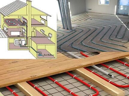
Despite the complexity of installation, underfloor heating using a water circuit is considered one of the most cost-effective methods of heating a room. In order for the system to function as efficiently as possible and not cause failures, it is necessary to correctly calculate the pipes for heated floors - determine the length, loop pitch and circuit laying pattern.
The comfort of using water heating largely depends on these indicators. It is these questions that we will examine in our article - we will tell you how to choose the best option for pipes, taking into account the technical characteristics of each type. Also, after reading this article, you will be able to choose the correct installation step and calculate the required diameter and length of the heated floor contour for a specific room.
The content of the article:
Parameters for calculating the thermal loop
At the design stage, it is necessary to resolve a number of issues that determine design features warm floor and operating mode - select the thickness of the screed, pump and other necessary equipment.
The technical aspects of organizing a heating branch largely depend on its purpose. In addition to the purpose, to accurately calculate the footage of the water circuit, you will need a number of indicators: coverage area, heat flux density, coolant temperature, type of floor covering.
Pipe coverage area
When determining the dimensions of the base for laying pipes, take into account the space that is not cluttered with large equipment and built-in furniture. It is necessary to think in advance about the arrangement of objects in the room.
Heat flow and coolant temperature
Heat flux density is a calculated indicator characterizing the optimal amount of heat energy for heating a room. The value depends on a number of factors: thermal conductivity of walls, ceilings, glazing area, presence of insulation and air exchange rate. Based on the heat flow, the loop laying step is determined.
The maximum coolant temperature is 60 °C. However, the thickness of the screed and the floor covering reduce the temperature - in fact, about 30-35 ° C is observed on the floor surface. The difference between the temperature indicators at the input and output of the circuit should not exceed 5 °C.
Type of flooring
The finish affects the efficiency of the system. Optimal thermal conductivity of tiles and porcelain stoneware - the surface heats up quickly.A good indicator of the efficiency of the water circuit when using laminate and linoleum without a thermal insulation layer. Wooden coverings have the lowest thermal conductivity.
The degree of heat transfer also depends on the filling material. The system is most effective when using heavy concrete with natural aggregate, for example, fine sea pebbles.
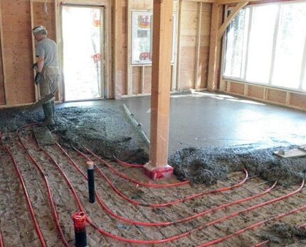
When calculating pipes for heated floors, you should take into account the established standards for the temperature regime of the coating:
- 29 °C - living room;
- 33 °C – rooms with high humidity;
- 35 °C – passage zones and cold zones – areas along the end walls.
The climatic features of the region will play an important role in determining the density of the water circuit. When calculating heat loss, the minimum temperature in winter must be taken into account.
As practice shows, preliminary insulation of the entire house will help reduce the load. It makes sense to first thermally insulate the room, and then start calculating heat loss and parameters of the pipe circuit.
Assessment of technical properties when choosing pipes
Due to non-standard operating conditions, high demands are placed on the material and size of the water floor coil:
- chemical inertness, resistance to corrosion processes;
- Absolutely smooth internal coating, not prone to the formation of limescale build-up;
- strength – the walls are constantly exposed to the coolant from the inside, and the screed from the outside; the pipe must withstand a pressure of up to 10 bar.
It is desirable that the heating branch have a small specific gravity.The water floor pie already places a significant load on the ceiling, and a heavy pipeline will only aggravate the situation.
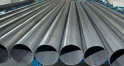
Three categories of rolled pipes meet the listed requirements to one degree or another: cross-linked polyethylene, metal-plastic, and copper.
Option #1 - cross-linked polyethylene (PEX)
The material has a mesh wide-cell structure of molecular bonds. Modified polyethylene differs from conventional polyethylene in the presence of both longitudinal and transverse ligaments. This structure increases specific gravity, mechanical strength and chemical resistance.
A water circuit made of PEX pipes has a number of advantages:
- high elasticity, allowing the installation of a coil with a small bend radius;
- safety – when heated, the material does not emit harmful components;
- heat resistance: softening – from 150 °C, melting – 200 °C, combustion – 400 °C;
- maintains structure during temperature fluctuations;
- damage resistance - biological destroyers and chemical reagents.
The pipeline retains its original throughput - no sediment is deposited on the walls. The estimated service life of a PEX circuit is 50 years.
There are four product groups:
- PEX-a – peroxide cross-linking. The most durable and uniform structure with a bond density of up to 75% is achieved.
- PEX-b – silane cross-linking. The technology uses silanides - toxic substances that are unacceptable for household use. Manufacturers of plumbing products replace it with a safe reagent. Pipes with a hygienic certificate are acceptable for installation. Crosslink density – 65-70%.
- PEX-c – radiation method. Polyethylene is irradiated with a stream of gamma rays or an electron. As a result, the bonds are compacted up to 60%. Disadvantages of PEX-c: unsafe use, uneven cross-linking.
- PEX-d – nitriding. The reaction to create a network occurs due to nitrogen radicals. The output is a material with a crosslink density of about 60-70%.
The strength characteristics of PEX pipes depend on the method of cross-linking polyethylene.
If you have decided on cross-linked polyethylene pipes, we recommend that you familiarize yourself with arrangement rules underfloor heating systems from them.
Option #2 - metal-plastic
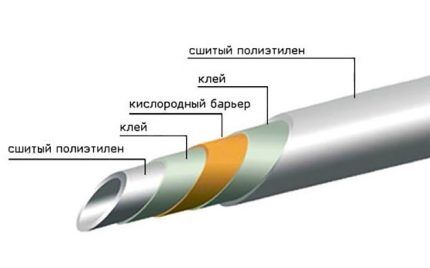
The leader in rolled pipes for installing heated floors is metal-plastic. Structurally, the material includes five layers.
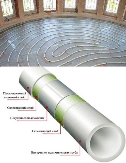
The metal increases the strength of the line, reduces the rate of thermal expansion and acts as an anti-diffusion barrier - it blocks the flow of oxygen to the coolant.
Features of metal-plastic pipes:
- good thermal conductivity;
- ability to maintain a given configuration;
- operating temperature with preservation of properties – 110 °C;
- low specific gravity;
- noiseless movement of the coolant;
- safety of use;
- corrosion resistance;
- service life – up to 50 years.
The disadvantage of composite pipes is the inadmissibility of bending about the axis.Repeated twisting risks damaging the aluminum layer. We recommend that you read correct installation technology metal-plastic pipes, which will help avoid damage.
Option #3 - copper pipes
In terms of technical and operational characteristics, yellow metal will be the best choice. However, its demand is limited by its high cost.
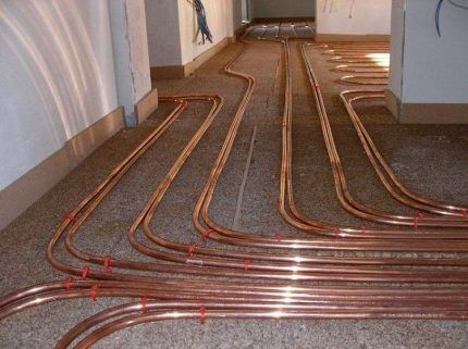
In addition to being expensive, copper piping has an additional disadvantage - complexity installation. To bend the contour you will need a press machine or pipe bender.
Option #4 - polypropylene and stainless steel
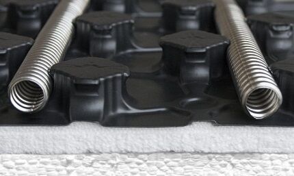
Sometimes a heating branch is created from polypropylene or stainless steel corrugated pipes. The first option is affordable, but quite rigid in bending - the minimum radius is eight times the diameter of the product.
This means that pipes with a standard size of 23 mm will have to be placed at a distance of 368 mm from each other - an increased laying step will not ensure uniform heating.
Possible ways to lay out the contour
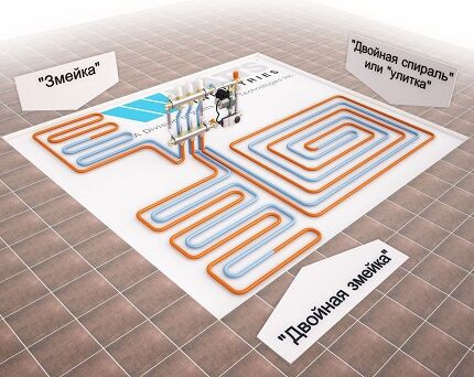
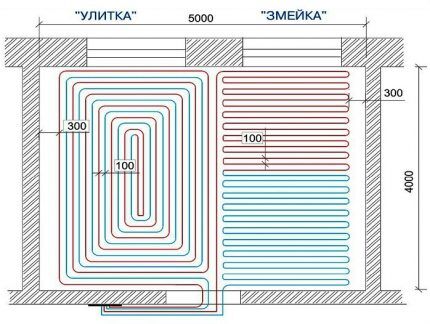
In order to determine the pipe consumption for arranging a heated floor, you should decide on the layout of the water circuit. The main task of planning the layout is to ensure uniform heating, taking into account the cold and unheated areas of the room.
Method #1 - snake
The coolant is supplied to the system along the wall, passes through the coil and returns to distribution manifold. In this case, half of the room is heated with hot water, and the rest with cooled water.
When laying with a snake, it is impossible to achieve uniform heating - the temperature difference can reach 10 ° C. The method is applicable in narrow spaces.
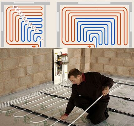
The double snake allows for a softer temperature transition. The forward and reverse circuits run parallel to each other.
Method #2 - snail or spiral
This is considered the optimal scheme to ensure uniform heating of the floor covering. Direct and reverse branches are laid alternately.
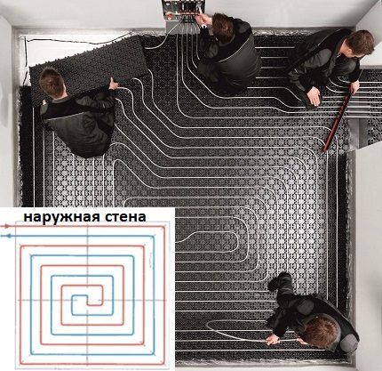
For large areas, a combined scheme is implemented. The surface is divided into sectors and a separate circuit is developed for each, leading to a common collector. In the center of the room the pipeline is laid out like a snail, and along the outer walls - like a snake.
We have another article on our website in which we discussed in detail installation diagrams underfloor heating and provided recommendations on choosing the optimal option depending on the characteristics of a particular room.
Pipe calculation method
In order not to get confused in the calculations, we suggest dividing the solution to the problem into several stages.First of all, it is necessary to estimate the heat loss of the room, determine the laying step, and then calculate the length of the heating circuit.
Principles of circuit design
When starting calculations and creating a sketch, you should familiarize yourself with the basic rules for the location of the water circuit:
- It is advisable to lay pipes along the window opening - this will significantly reduce the heat loss of the building.
- The recommended coverage area of one water circuit is 20 square meters. m. In large rooms it is necessary to divide the space into zones and lay a separate heating branch for each.
- The distance from the wall to the first branch is 25 cm. The permissible pitch of pipe turns in the center of the room is up to 30 cm, along the edges and in cold zones – 10-15 cm.
- Determining the maximum pipe length for underfloor heating should be based on the diameter of the coil.
For a circuit with a cross-section of 16 mm, no more than 90 m is allowed, the limit for a pipeline with a thickness of 20 mm is 120 m. Compliance with the standards will ensure normal hydraulic pressure in the system.
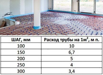
Basic formula with explanations
The length of the heated floor contour is calculated using the formula:
L=S/n*1,1+k,
Where:
- L — the required length of the heating main;
- S – covered floor area;
- n – laying step;
- 1,1 – standard factor of ten percent bending reserve;
- k – distance of the collector from the floor – the distance to the supply and return circuit wiring is taken into account.
The coverage area and the pitch of the turns will play a decisive role.
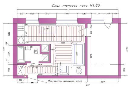
It should be remembered that placing heating pipes under large household appliances and built-in furniture is not recommended. The parameters of the designated items must be subtracted from the total area.
To select the optimal distance between the branches, it is necessary to carry out more complex mathematical manipulations, operating with the heat loss of the room.
Thermal engineering calculation with determination of the circuit pitch
The density of the pipes directly affects the amount of heat flow emanating from the heating system. To determine the required load, it is necessary to calculate the heat costs in winter.
The power of the heating system is determined by the formula:
M=1.2*Q,
Where:
- M – circuit performance;
- Q – total heat loss of the room.
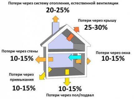
The value of Q can be decomposed into components: energy consumption through the enclosing structures and costs caused by the operation of the ventilation system. Let's figure out how to calculate each of the indicators.
Heat loss through building elements
It is necessary to determine the heat energy consumption for all enclosing structures: walls, ceilings, windows, doors, etc. Calculation formula:
Q1=(S/R)*Δt,
Where:
- S – area of the element;
- R – thermal resistance;
- Δt – the difference between the temperature indoors and outdoors.
When determining Δt, the indicator for the coldest time of the year is used.
Thermal resistance is calculated as follows:
R=A/Kt,
Where:
- A – layer thickness, m;
- CT – thermal conductivity coefficient, W/m*K.
For combined elements of a structure, the resistance of all layers must be summed up.
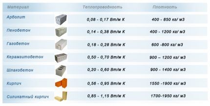
We have provided more values of the thermal conductivity coefficient for the most popular building materials in the table contained in the next article.
Ventilation heat loss
To calculate the indicator, the formula is used:
Q2=(V*K/3600)*C*P*Δt,
Where:
- V – volume of the room, cubic meters. m;
- K – air exchange rate;
- C – specific heat capacity of air, J/kg*K;
- P – air density at normal room temperature – 20 °C.
The air exchange rate of most rooms is equal to one. The exception is for houses with internal vapor barrier - to maintain a normal microclimate, the air must be renewed twice an hour.
Specific heat capacity is a reference indicator. At standard temperature without pressure, the value is 1005 J/kg*K.
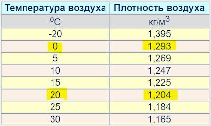
Total heat loss
The total amount of heat loss in the room will be equal to: Q=Q1*1.1+Q2. Coefficient 1.1 – an increase in energy costs by 10% due to air infiltration through cracks and leaks in building structures.
Multiplying the obtained value by 1.2, we obtain the required power of the heated floor to compensate for heat loss. Using a graph of heat flow versus coolant temperature, you can determine the appropriate pipe pitch and diameter.
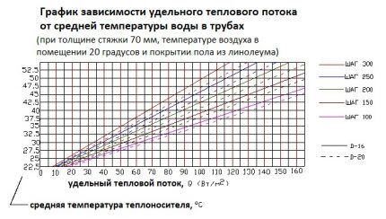
The data is relevant for heated floors on a sand-cement screed with a thickness of 7 mm, the coating material is ceramic tiles. For other conditions, values must be adjusted to account for the thermal conductivity of the finish.
For example, when laying carpet, the coolant temperature should be increased by 4-5 °C. Each additional centimeter of screed reduces heat transfer by 5-8%.
Final choice of contour length
Knowing the pitch of laying the coils and the area covered, it is easy to determine the flow rate of the pipes. If the obtained value is greater than the permissible value, then it is necessary to install several circuits.
It is optimal if the loops are the same length - there is no need to adjust or balance anything. However, in practice, it is more often necessary to rupture the heating main into different sections.
A specific example of calculating a heating branch
Let's assume that you need to determine the parameters of the thermal circuit for a house with an area of 60 square meters.
For the calculation you will need the following data and characteristics:
- room dimensions: height – 2.7 m, length and width – 10 and 6 m, respectively;
- the house has 5 metal-plastic windows of 2 sq. m;
- external walls - aerated concrete, thickness - 50 cm, Kt = 0.20 W/mK;
- additional wall insulation – polystyrene foam 5 cm, Kt=0.041 W/mK;
- ceiling material – reinforced concrete slab, thickness – 20 cm, Kt=1.69 W/mK;
- attic insulation – 5 cm thick polystyrene foam boards;
- dimensions of the entrance door - 0.9 * 2.05 m, thermal insulation - polyurethane foam, layer - 10 cm, Kt = 0.035 W/mK.
Next, let's look at a step-by-step example of performing the calculation.
Step 1 - calculation of heat loss through structural elements
Thermal resistance of wall materials:
- aerated concrete: R1=0.5/0.20=2.5 sq.m*K/W;
- expanded polystyrene: R2=0.05/0.041=1.22 sq.m*K/W.
The thermal resistance of the wall as a whole is: 2.5 + 1.22 = 3.57 sq. m*K/W. We take the average temperature in the house to be +23 °C, the minimum temperature outside is 25 °C with a minus sign. The difference in indicators is 48 °C.
Calculation of the total wall area: S1=2.7*10*2+2.7*6*2=86.4 sq. m. From the obtained indicator it is necessary to subtract the size of the windows and doors: S2 = 86.4-10-1.85 = 74.55 sq. m. m.
Substituting the obtained indicators into the formula, we obtain wall heat loss: Qc=74.55/3.57*48=1002 W
The final thermal resistance of the ceiling is: 0.2/1.69+0.05/0.041=0.118+1.22=1.338 sq. m*K/W. Heat loss will be: Qp=60/1.338*48=2152 W.
To calculate heat leakage through windows, it is necessary to determine the weighted average value of the thermal resistance of the materials: double-glazed window - 0.5 and profile - 0.56 sq. m*K/W respectively.
Ro=0.56*0.1+0.5*0.9=0.56 sq.m*K/W. Here 0.1 and 0.9 are the proportion of each material in the window structure.
Window heat loss: Qо=10/0.56*48=857 W.
Taking into account the thermal insulation of the door, its thermal resistance will be: Rd=0.1/0.035=2.86 sq. m*K/W. Qd=(0.9*2.05)/2.86*48=31 W.
The total heat loss through the enclosing elements is: 1002+2152+857+31=4042 W. The result must be increased by 10%: 4042*1.1=4446 W.
Step 2 - heat for heating + general heat loss
First, let's calculate the heat consumption for heating the incoming air. Room volume: 2.7*10*6=162 cubic meters. m. Accordingly, ventilation heat loss will be: (162*1/3600)*1005*1.19*48=2583 W.
According to these room parameters, the total heat costs will be: Q=4446+2583=7029 W.
Step 3 - required power of the thermal circuit
We calculate the optimal circuit power required to compensate for heat loss: N=1.2*7029=8435 W.
Next: q=N/S=8435/60=141 W/sq.m.
Step 4 - determining the laying pitch and contour length
The resulting value is compared with the dependence graph. If the coolant temperature in the system is 40 °C, then a circuit with the following parameters is suitable: pitch – 100 mm, diameter – 20 mm.
If water heated to 50 °C circulates in the main, then the interval between branches can be increased to 15 cm and a pipe with a cross-section of 16 mm can be used.
We calculate the length of the contour: L=60/0.15*1.1=440 m.
Separately, it is necessary to take into account the distance from the collectors to the heating system.
As can be seen from the calculations, to install a water floor you will have to make at least four heating loops. How to properly lay and secure pipes, as well as other installation secrets, we reviewed here.
Conclusions and useful video on the topic
Visual video reviews will help you make a preliminary calculation of the length and pitch of the thermal circuit.
Choosing the most effective distance between branches of an underfloor heating system:
A guide on how to find out the length of the loop of the heated floor in use:
The calculation method cannot be called simple. At the same time, many factors affecting the circuit parameters should be taken into account. If you plan to use the water floor as the only source of heat, then it is better to entrust this work to professionals - mistakes at the planning stage can be costly.
Do you calculate the required footage of pipes for heated floors and their optimal diameter yourself? Maybe you still have questions that we did not cover in this material? Ask them to our experts in the comments section.
If you specialize in calculating pipes for arranging water heated floors and you have something to add to the material presented above, please write your comments below under the article.


Everything is well described, competently. But I want to warn everyone who is going to make a warm floor, they must choose the right floor covering itself. I didn’t know, I didn’t read it anywhere, and I bought the most ordinary floor tiles. And it started to crack. As the heated floor begins to work, new cracks appear. The disorder is complete. Maybe my story will warn someone and help them not to make mistakes.
Hello. The reason is not the tile. Most likely, you did not wait for the screed or tile adhesive to dry completely after installation. When you turn on the TP, drying accelerates, the tile pulls and, accordingly, it cracks. The temperature is not high enough to break the ceramic tiles. Here is either my version or the version with defective tiles. There are no special products for TP.
It may also be that the glue was not used for heated floors.
It’s a pity that this note didn’t catch my eye when I was planning to make a heated floor in my country house. I trusted a not very good team of workers, and they built a heating branch out of stainless steel.And now everything is as described by you - the heat is distributed unevenly across the rooms, because the pipes are far from each other. We'll have to redo it.