Calculation of water heating: formulas, rules, examples of implementation
Using water as a coolant in a heating system is one of the most popular options to provide your home with heat during the cold season.You just need to properly design and then install the system. Otherwise, heating will be ineffective at high fuel costs, which, you see, is extremely uninteresting at today's energy prices.
It is impossible to independently calculate water heating (hereinafter referred to as WHE) without using specialized programs, since the calculations use complex expressions, the values of which cannot be determined using a conventional calculator. In this article, we will analyze in detail the algorithm for performing calculations, present the formulas used, and consider the progress of the calculations using a specific example.
We will supplement the presented material with tables with values and reference indicators that are needed when carrying out calculations, thematic photos and a video that demonstrates a clear example of calculations using the program.
The content of the article:
Calculation of the heat balance of a housing structure
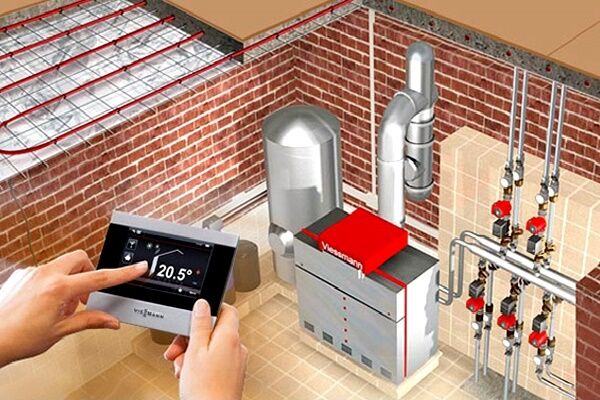
To implement a heating installation where water is the circulating medium, it is necessary to first make precise hydraulic calculations.
When developing and implementing any heating type system, it is necessary to know the heat balance (hereinafter referred to as TB).Knowing the thermal power to maintain the temperature in the room, you can choose the right equipment and correctly distribute its load.
In winter, the room suffers certain heat losses (hereinafter referred to as HL). The bulk of energy exits through enclosing elements and ventilation openings. Minor costs are incurred for infiltration, heating of objects, etc.
TP depend on the layers that make up the enclosing structures (hereinafter referred to as OK). Modern building materials, in particular insulation materials, have low thermal conductivity coefficient (hereinafter referred to as CT), due to which less heat is lost through them. For houses of the same area, but with different OK structures, heat costs will differ.
In addition to determining the TP, it is important to calculate the TB of the home. The indicator takes into account not only the amount of energy leaving the room, but also the amount of power required to maintain certain temperature levels in the house.
The most accurate results are provided by specialized programs developed for builders. Thanks to them, it is possible to take into account more factors influencing TP.

With high accuracy, you can calculate the TP of a home using formulas.
The total heating costs of the house are calculated using the equation:
Q = Qok +Qv,
Where Qok - the amount of heat leaving the room through OK; Qv — heat ventilation costs.
Ventilation losses are taken into account if the air entering the room has a lower temperature.
Calculations usually take into account OKs with one side facing the street. These are the external walls, floor, roof, doors and windows.
General TP Qok equal to the sum of the TP of each OK, that is:
Qok = ∑Qst +∑Qokn +∑Qdv +∑Qptl +∑Qpl,
Where:
- Qst — value of TP of walls;
- Qokn — TP windows;
- Qdv — TP doors;
- Qptl — ceiling TP;
- Qpl — TP floor.
If the floor or ceiling has a different structure over the entire area, then the TP is calculated for each section separately.
Calculation of heat loss using OK
For calculations you will need the following information:
- structure of walls, materials used, their thickness, CT;
- outside temperature during an extremely cold five-day winter in the city;
- area OK;
- orientation OK;
- recommended temperature in the home in winter.
To calculate TC you need to find the total thermal resistance ROK. To do this you need to find out the thermal resistance R1, R2, R3, …, Rn each layer is OK.
R-factorn calculated by the formula:
Rn = B/k,
In the formula: B — layer thickness OK in mm, k — CT scan of each layer.
The total R can be determined by the expression:
R = ∑Rn
Manufacturers of doors and windows usually indicate the R coefficient in the product data sheet, so there is no need to calculate it separately.

The general formula for calculating TP through OK is as follows:
Qok = ∑S × (tvnt -tnar) × R × l,
In the expression:
- S — area OK, m2;
- tvnt - desired room temperature;
- tnar — outside air temperature;
- R — resistance coefficient, calculated separately or taken from the product data sheet;
- l — a clarifying coefficient that takes into account the orientation of the walls relative to the cardinal directions.
Calculation of TB allows you to select equipment of the required power, which will eliminate the possibility of heat deficiency or excess. The deficit of thermal energy is compensated by increasing the air flow through ventilation, the excess - by installing additional heating equipment.
Thermal costs of ventilation
The general formula for calculating TP ventilation is as follows:
Qv = 0.28 × Ln × pvnt × c × (tvnt -tnar),
In an expression, variables have the following meaning:
- Ln — consumption of incoming air;
- pvnt — air density at a certain temperature in the room;
- c — heat capacity of air;
- tvnt - temperature in the house;
- tnar — outside air temperature.
If ventilation is installed in the building, then parameter Ln taken from the technical specifications for the device. If there is no ventilation, then a standard specific air exchange rate of 3 m is taken.3 at one o'clock.
Based on this, Ln calculated by the formula:
Ln = 3 × Spl,
In expression Spl - floor area.

Next you need to calculate the air density pvnt at a given room temperature tvnt.
This can be done using the formula:
pvnt = 353/(273+tvnt),
Specific heat capacity c = 1.0005.
If ventilation or infiltration is unorganized, or there are cracks or holes in the walls, then the calculation of TP through the holes should be entrusted to special programs.
In our other article we provided detailed example of thermal engineering calculation buildings with specific examples and formulas.
Example of heat balance calculation
Consider a house 2.5 m high, 6 m wide and 8 m long, located in the city of Okha in the Sakhalin region, where on an extremely cold 5-day day the thermometer drops to -29 degrees.
As a result of the measurement, the soil temperature was determined to be +5. The recommended temperature inside the structure is +21 degrees.

The walls of the house in question consist of:
- brickwork thickness B=0.51 m, CT k=0.64;
- mineral wool B=0.05 m, k=0.05;
- facing B=0.09 m, k=0.26.
When determining k, it is better to use the tables presented on the manufacturer’s website or find information in the product data sheet.

The flooring consists of the following layers:
- OSB boards B=0.1 m, k=0.13;
- mineral wool B=0.05 m, k=0.047;
- cement screeds B=0.05 m, k=0.58;
- expanded polystyrene B=0.06 m, k=0.043.
There is no basement in the house, and the floor has the same structure throughout the entire area.
The ceiling consists of layers:
- plasterboard sheets B=0.025 m, k= 0.21;
- insulation B=0.05 m, k=0.14;
- roofing B=0.05 m, k=0.043.
There are no exits to the attic.
The house has only 6 double-chamber windows with I-glass and argon. From the technical data sheet for the product it is known that R=0.7. The windows have dimensions of 1.1x1.4 m.
The doors have dimensions of 1x2.2 m, R = 0.36.
Step #1 - calculation of wall heat loss
The walls throughout the area consist of three layers. First, let's calculate their total thermal resistance.
Why use the formula:
R = ∑Rn,
and the expression:
Rn = B/k
Taking into account the initial information, we get:
Rst = 0.51/0.64 + 0.05/0.05 + 0.09/0.26 = 0.79 +1 + 0.35 = 2.14
Having found out R, you can begin to calculate the TP of the northern, southern, eastern and western walls.

Let's calculate the area of the northern wall:
Ssev.sten = 8 × 2.5 = 20
Then, substituting into the formula Qok = ∑S × (tvnt -tnar) × R × l and taking into account that l=1.1, we get:
Qsev.sten = 20 × (21 + 29) × 1.1 × 2.14 = 2354
Area of the southern wall Syuch.st = Ssev.st = 20.
There are no built-in windows or doors in the wall, therefore, taking into account the coefficient l=1, we obtain the following TP:
Qyuch.st = 20 × (21 +29) × 1 × 2.14 = 2140
For the western and eastern walls, the coefficient is l=1.05. Therefore, you can find the total area of these walls, that is:
Szap.st +Svost.st = 2 × 2.5 × 6 = 30
There are 6 windows and one door built into the walls. Let's calculate the total area of windows and S doors:
Sokn = 1.1 × 1.4 × 6 = 9.24
Sdv = 1 × 2.2 = 2.2
Let us define S walls without taking into account S windows and doors:
Svost+zap = 30 — 9.24 — 2.2 = 18.56
Let's calculate the total TP of the eastern and western walls:
Qvost+zap =18.56 × (21 +29) × 2.14 × 1.05 = 2085
Having received the results, let's calculate the amount of heat escaping through the walls:
Qst = Qsev.st + Qyuch.st +Qvost+zap = 2140 + 2085 + 2354 = 6579
In total, the total TP of the walls is 6 kW.
Step #2 - calculating the TP of windows and doors
The windows are located on the eastern and western walls, so when calculating, the coefficient is l=1.05. It is known that the structure of all structures is the same and R = 0.7.
Using the area values given above, we get:
Qokn = 9.24 × (21 +29) × 1.05 × 0.7 = 340
Knowing that for doors R=0.36 and S=2.2, we determine their TP:
Qdv = 2.2 × (21 +29) × 1.05 × 0.36 = 42
As a result, 340 W of heat comes out through the windows, and 42 W through the doors.
Step #3 - determining the TP of the floor and ceiling
Obviously, the area of the ceiling and floor will be the same, and is calculated as follows:
Spol = Sptl = 6 × 8 = 48
Let's calculate the total thermal resistance of the floor, taking into account its structure.
Rpol = 0.1/0.13 + 0.05/0.047 + 0.05/0.58 + 0.06/0.043 = 0.77 + 1.06 + 0.17 + 1.40 = 3.4
Knowing that the ground temperature tnar=+5 and taking into account the coefficient l=1, we calculate Q of the floor:
Qpol = 48 × (21 — 5) × 1 × 3.4 = 2611
Rounding up, we find that the floor heat loss is about 3 kW.

Let's determine the thermal resistance of the ceiling Rptl and his Q:
- Rptl = 0.025/0.21 + 0.05/0.14 + 0.05/0.043 = 0.12 + 0.71 + 0.35 = 1.18
- Qptl = 48 × (21 +29) × 1 × 1.18 = 2832
It follows that almost 6 kW goes through the ceiling and floor.
Step #4 - calculation of ventilation TP
Ventilation in the room is organized and calculated using the formula:
Qv = 0.28 × Ln × pvnt × c × (tvnt -tnar)
Based on the technical characteristics, the specific heat transfer is 3 cubic meters per hour, that is:
Ln = 3 × 48 = 144.
To calculate the density we use the formula:
pvnt = 353/(273+tvnt).
The estimated room temperature is +21 degrees.

Substituting known values, we get:
pvnt = 353/(273+21) = 1.2
Let's substitute the resulting numbers into the above formula:
Qv = 0.28 × 144 × 1.2 × 1.005 × (21 — 29) = 2431
Taking into account the TP for ventilation, the total Q of the building will be:
Q = 7000 + 6000 + 3000 = 16000.
Converting to kW, we get a total heat loss of 16 kW.
Features of calculating SVO
After finding the TP indicator, they proceed to hydraulic calculation (hereinafter referred to as GR).
Based on it, information about the following indicators is obtained:
- the optimal diameter of the pipes, which, during pressure drops, will be able to pass a given amount of coolant;
- coolant flow in a certain area;
- water movement speed;
- resistivity value.
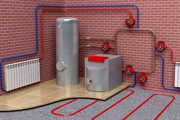
Before starting the calculations, to simplify the calculations, draw a spatial diagram of the system, on which all its elements are arranged parallel to each other.

Let's consider the main stages of water heating calculations.
GR of the main circulation ring
The method for calculating GR is based on the assumption that the temperature differences are the same in all risers and branches.
The calculation algorithm is as follows:
- In the diagram shown, taking into account heat loss, the thermal loads acting on heating devices and risers are applied.
- Based on the diagram, the main circulation ring (hereinafter referred to as the MCC) is selected. The peculiarity of this ring is that in it the circulation pressure per unit length of the ring takes on the lowest value.
- The FCC is divided into sections with constant heat consumption. For each section, indicate the number, thermal load, diameter and length.
In a vertical system of a single-pipe type, the ring through which the most loaded riser passes during dead-end or associated movement of water along the mains is taken as the main circulation circuit.We talked in more detail about linking circulation rings in a single-pipe system and choosing the main one in the next article. We paid special attention to the order of calculations, using a specific example for clarity.

In a horizontal single-pipe type system, the main circulation circuit should have the lowest circulation pressure and a unit length of the ring. For systems with natural circulation the situation is similar.
When developing risers of a vertical system of a single-pipe type, flow-through, flow-regulated risers, which incorporate unified components, are considered as a single circuit. For risers with closing sections, separation is carried out, taking into account the distribution of water in the pipeline of each instrument unit.
Water consumption in a given area is calculated using the formula:
Gkont = (3.6 × Qkont × β1 × β2)/((tr -t0) × c)
In the expression, the alphabetic characters take the following meanings:
- Qkont — thermal load of the circuit;
- β1, β2 — additional tabular coefficients taking into account heat transfer in the room;
- c — heat capacity of water, equal to 4.187;
- tr — water temperature in the supply line;
- t0 — water temperature in the return line.
Having determined the diameter and amount of water, it is necessary to find out the speed of its movement and the value of the specific resistance R. All calculations are most conveniently carried out using special programs.
GR secondary circulation ring
After GR of the main ring, the pressure in the small circulation ring formed through its nearest risers is determined, taking into account that pressure losses can differ by no more than 15% in a dead-end circuit and by no more than 5% in a passing circuit.
If it is impossible to correlate the pressure loss, install a throttle washer, the diameter of which is calculated using software methods.
Calculation of radiator batteries
Let's return to the house plan above. Through calculations, it was revealed that 16 kW of energy will be required to maintain the thermal balance. The house in question has 6 rooms for different purposes - a living room, a bathroom, a kitchen, a bedroom, a corridor, and an entrance hall.
Based on the dimensions of the structure, you can calculate the volume V:
V=6×8×2.5=120 m3
Next you need to find the amount of thermal power per m3. To do this, Q must be divided by the found volume, that is:
P=16000/120=133 W per m3
Next, you need to determine how much heating power is required for one room. In the diagram, the area of each room has already been calculated.
Let's determine the volume:
- bathroom – 4.19×2.5=10.47;
- living room – 13.83×2.5=34.58;
- kitchen – 9.43×2.5=23.58;
- bedroom – 10.33×2.5=25.83;
- corridor – 4.10×2.5=10.25;
- hallway – 5.8×2.5=14.5.
The calculations also need to take into account rooms in which there are no heating radiators, for example, a corridor.

Let's determine the required amount of heat for each room by multiplying the volume of the room by the R index.
Let's get the required power:
- for the bathroom — 10.47×133=1392 W;
- for living room — 34.58×133=4599 W;
- for kitchen — 23.58×133=3136 W;
- for the bedroom — 25.83×133=3435 W;
- for the corridor — 10.25×133=1363 W;
- for the hallway — 14.5×133=1889 W.
Let's start calculating radiator batteries. We will use aluminum radiators, the height of which is 60 cm, the power at a temperature of 70 is 150 W.
Let's calculate the required number of radiator batteries:
- bathroom — 1392/150=10;
- living room — 4599/150=31;
- kitchen — 3136/150=21;
- bedroom — 3435/150=23;
- hallway — 1889/150=13.
Total required: 10+31+21+23+13=98 radiator batteries.
We also have other articles on our website in which we examined in detail the procedure for performing thermal calculations of a heating system, step-by-step calculations of the power of radiators and heating pipes. And if your system requires heated floors, then you will need to perform additional calculations.
All these issues are covered in more detail in our following articles:
- Thermal calculation of a heating system: how to correctly calculate the load on the system
- Calculation of heating radiators: how to calculate the required number and power of batteries
- Calculation of pipe volume: principles of calculations and rules for making calculations in liters and cubic meters
- How to calculate a heated floor using a water system as an example
- Calculation of pipes for heated floors: types of pipes, methods and laying step + calculation of flow rate
Conclusions and useful video on the topic
In the video you can see an example of calculating water heating, which is carried out using the Valtec program:
Hydraulic calculations are best carried out using special programs that guarantee high accuracy of calculations and take into account all the nuances of the design.
Do you specialize in calculating heating systems using water as a coolant and want to supplement our article with useful formulas and share professional secrets?
Or maybe you want to focus on additional calculations or point out inaccuracies in our calculations? Please write your comments and recommendations in the block below the article.


To be honest, I didn’t really bother with the calculations when I was making my own heating. For me, all these formulas are an Egyptian execution. This is for engineers, estimators, and all that. Of course, this approach will allow you to accurately calculate and take into account all the nuances of heating.
I polished the system over the course of several more years, at random, so to speak. In the hall I added fins for the radiators, but in the kitchen, on the contrary, I reduced them, it was hot. I foresaw this possibility and took it into account when connecting.
The fact of the matter is that it is not always possible to finish it so that the system works adequately. There is no desire to do the calculations yourself - you can trust the specialists.