How to connect a light bulb through a switch: diagrams and connection rules
Have you decided to install electrical wiring in your new dacha yourself or to upgrade the existing network in your apartment? Agree, there are nuances in this area that you should thoroughly understand for your own safety. In addition, self-made electricians must ensure the flawless operation of the devices.
We are ready to tell you in great detail how to connect a light bulb through a switch. In implementing such a solution, a number of practice-tested techniques are used, which you will become familiar with while reading the article.
Here you will find a lot of useful information. Possession of information will give both confidence and strength. Graphic materials and videos will help you thoroughly understand the issue.
The content of the article:
- Electrical Safety Measures
- Tool for getting the job done
- Recommended Cables and Wires
- Application of junction box
- Removing insulation from wiring
- Nuances of twist formation
- Correct installation of the switch
- Types of household switches
- Types of lamps for home use
- Ways to power a light bulb through a switch
- Conclusions and useful video on the topic
Electrical Safety Measures
Previously, before starting the installation of switches, lighting fixtures, connecting them to each other and the network, it is necessary to de-energize the 220V power supply to that part of the home wiring where electrical installation work is expected to be carried out.
This is done at the input electrical panel by disabling the general or corresponding group switch.

If access to the panel by unauthorized persons is possible during the installation process (for example, located on the staircase of an apartment building), it is necessary to place warning poster "Do not turn on!".
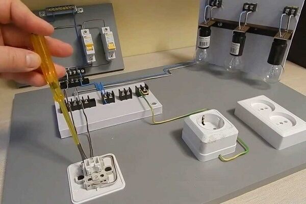
You need to make sure that there is no voltage on the exposed contacts of operating electrical appliances and wiring immediately before work. The easiest way to do this at home is with indicator screwdriver, the serviceability of which is checked from the working network shortly before testing.
It is recommended that before handling contacts and wires with bare hands, once again make sure that there is no voltage by touching all of them alternately with the back of your hand and the fingers of your right hand. Dry, intact skin on the back of the hand has increased resistance to electrical current.
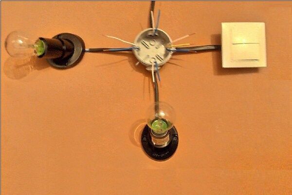
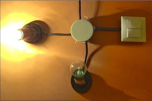
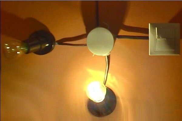
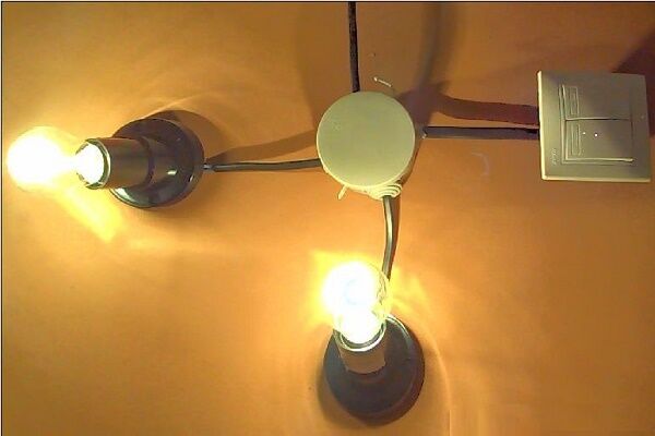
The essence of connecting a lamp through a switch can be visualized on the demonstration stand:
Tool for getting the job done
In the process of performing electrical work, a home handyman will need a set of the following installation tools:
- Sharp knife.
- Pliers (pliers).
- Side cutters.
- Slotted screwdrivers, thin and medium, possibly Phillips medium.
Electrical tape may be required to insulate the wire connections inside the junction box or light housing. In these cases, it is recommended to use CB tape. Over time, it does not melt or stick to the constantly heating contacts it insulates, but only dries out. If necessary, crumble well with pliers.

Great if you have a special one wire stripper tool or wire cutters with slots for stripping insulation. In the absence of such devices and a large amount of work, you can get by with a folk remedy by modifying the side cutters.
To do this, use a file to make opposite cuts in the cutting edges closer to the hinge, which together should form a hole slightly larger than the diameter of the exposed wire strand.
Recommended Cables and Wires
For new installations of home electrical lighting networks, it is recommended to use VVGng cables with single-wire copper, 1.5 sq. mm cross-section, in non-flammable insulation with conductors of different colors:
- blue – zero working,
- yellow with a green stripe along its length – zero protective (grounding),
- any other color - phase.
When installing, it is advisable to maintain a combination of color uniformity and their functional purpose. This requirement will protect and also simplify further maintenance of the electrical wiring.

In houses where the wiring is still made of aluminum, replacement of individual sections of lighting lines embedded under plaster must be done with APPV-1.5 wire having aluminum cores or a similar cable when laid open. The same material is used due to oxidation of the aluminum and copper contacts inside the junction boxes.
If it is possible to replace twists with terminal connections, the use of copper wiring is allowed. It is strongly NOT recommended to use any cables or wires with stranded (soft) cores.
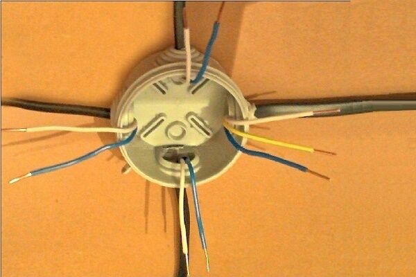
Application of junction box
Cables and wires do not go directly from the panel to electrical appliances, from switches to light bulbs. All outgoing and incoming lines of electrical equipment are found in specific installation units called branch boxes. There they communicate in a certain way.
With rules installation of branch boxes, also called unsoldered, branch, or unsoldered in electricians' slang, will be introduced in the following article. We recommend that you read the useful material.
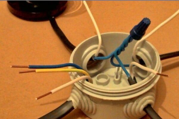
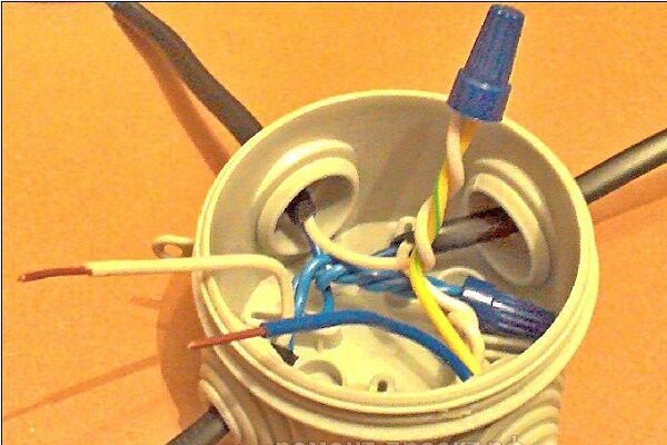
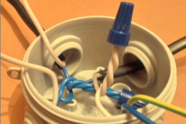
Most often, boxes have empty space inside. The wires of different lines are then connected to each other using twists.To ensure reliability, it is recommended to treat the tails of the connections with special welding. Copper conductors can simply be soldered.
Before laying inside, open contacts are insulated from each other with cotton tape. You can screw special insulating clamps onto the twisted wires. Here, insulating tape is no longer needed.

If the box is equipped with screw terminals, the contacts are then made using them. Such devices allow you to connect aluminum and copper conductors. Clamp terminals can be used, but this is only if there is sufficient space for laying the ends of the wires connected by them.
Removing insulation from wiring
To remove part of the external insulation of the VVGng cable, a knife is required. It should be so sharp that even an inexperienced DIYer can make confident cuts.
The first cut is made from the end along the shell by 3-4 cm. After this, with one hand they grasp the bundle of freed ends of the wires, and with the other they pull the cut shirt. Then she breaks down herself.
The depth of the tear is such that the freed tails of the wires are of the maximum length that the junction box, socket box or lighting fixture housing allows for installation. The reserve will serve you well in the future when loose contacts burn out.
The torn cable jacket is turned inside out and carefully, so as not to damage the insulation of the wires, cut off in a circle.
The veins are easiest to strip, of course, stripping tool - a stripper or at least side cutters with slots.In the absence of these, a knife is used in the same way as before. The use of simple side cutters is allowed. As a last resort, use the biting edges of pliers.

With light movements of the tool in a circle, they cut shallowly into the insulation and tighten it. The main thing is not to cut through the metal of the conductor, otherwise where there is damage, it will definitely break off. It would be good if it happened immediately, and not after installation.
The size of the exposed area is determined by the connection method. When these are screw terminals of a box, switch, chandelier or sconce, 0.5-1 cm may be sufficient. For twisting with the wiring of the lamp, 2-3 cm will be required.
If the strands are located in a junction box, the rule is that the bigger the better, especially without soldering or welding. Usually 3-5 cm.
When using screw-on insulating clamps, the clamping terminals are adjusted to the stripping length individually.
Nuances of twist formation
When twisting two wires, their exposed ends are folded in an “X” shape so that the intersection is at the beginning of the insulation. Then the ends of the veins are pinched with your fingers and twisted as much as possible. Next, the process is helped with pliers.
Three or more wires are connected in the same way. If the connection comes out both long and flexible, fold it in half, pressing it with pliers. A shorter twist requires less electrical tape.

The insulating tape begins to be applied from the factory insulation of the twisted wires to the width of the tape. After passing in one layer until the end of the bare tails, a couple more turns are made, as if wrapping up the air. This “void” is bent back into a twist - a protected end is obtained, and the second row is wound up with the obligatory approach to the main insulation of the cores.
Correct installation of the switch
By design, switches are available for indoor and outdoor installation. Modern outdoor switches are suitable for mounting on any surface without additional insulating supports. Internal switches are hidden in round sockets in the wall, equipped with special cups called socket boxes.
Learn more about how to install this mounting box in a concrete wall or plasterboard structure. written here. We advise you to read the proposed article before starting work.
Socket boxes are a standard electrical installation unit. They are also used to equip sockets, which is why they are called that. "Subswitches" wouldn't sound very good.
The correct location of the switch is considered to be one in which turning on occurs by pressing the upper part of the key, and turning off occurs by pressing the lower part. This gives even a short person the opportunity to react in an emergency situation and quickly turn off the power to an electrical device by hitting the key from top to bottom with his fingers.

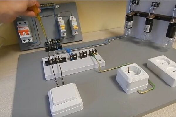
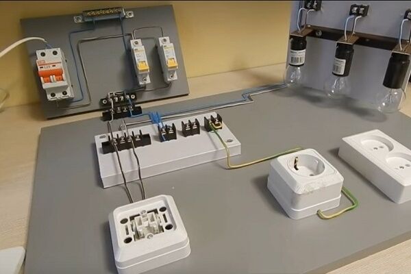
With proper connection, a phase wire comes to the switch from the junction box.Interrupting the phase wire circuit so that when the lamp is turned off there is no voltage - the main task of the switch.
The following photo selection illustrates the connection process clearly:
If the design of the device allows, inside the switch itself, the phase wire is connected to the upper terminals, and all outgoing conductors are connected to the lower contacts. This rule applies to the arrangement of any electrical installation.
Due to design features, exceptions to the general rules are pass-through and crossover switches, which are discussed below.
Types of household switches
There are a wide variety of switches used in modern home interiors. Introduces in detail the classification of light control devices one of the popular articlesposted on our website.

Based on the differences in their functionality, the following most common varieties are distinguished:
- Single-key switch – its mission is simple: “on/off”.
- Two-gang switch allows you to simultaneously control two independent lighting circuits.
- Three-key switch, accordingly, coordinates work in three directions.
- Switch-regulator (dimmer) not only turns it on and off, but also by pressing a key or turning the round knob that replaces it, smoothly adjusts the brightness of the lamps.
- Switch with regulator – a two- or three-key switch, which, in steps, by switching keys, controls the intensity of all light bulbs simultaneously.
- Single pass-through switch. The only key changes the phase between two wires. If voltage is applied to one, it is turned off from the other, and vice versa.
- Cross single switch. By changing the position of the key, it synchronously changes the direct connection of two lines to a cross one.
- Sensor switch. It has no levers - it starts and stops the flow of electricity by touching its surface with your fingers.
A motion sensor switch turns on the lamp automatically, reacting to a person passing by.
Types of lamps for home use
Tube progress keeps pace with switches. Their diversity is also impressive.

But here, too, some more popular types are defined:
- Incandescent lamps – rooted home light sources in a round glass bulb with a vacuum and a tungsten coil inside.
- Halogen lamps – the same incandescent lamps filled with a special gas. It increases service life and minimizes the size of their flasks. Disadvantage: When installing, you cannot touch the glass of the flask with your hands.
- Fluorescent daylight lamps – not very common at home, but also traditional lighting devices (hereinafter simply “fluorescent lamps”).
- Energy saving LED lamps, based on the name, they use the glow of groups of LEDs. They can be fixed into ordinary screw-in sockets (hereinafter simply “LED lamps”).
Energy-saving fluorescent light bulbs are increasingly replacing the usual ones. The operating principle is similar to fluorescent lamps. They are screwed in like incandescent lamps (hereinafter simply “energy-saving lamps”).
Ways to power a light bulb through a switch
Perhaps some of the schemes under consideration for the mutual connection of a household switch to a wall or ceiling light bulb will omit the details of supplying the neutral protective (grounding) wire. It seems that connecting it will not cause any difficulties.
In a standard electrical cable, this is a core with yellow insulation and a green stripe along it. The place where it is connected to the electrical appliance is indicated by a sign 
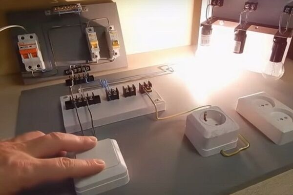
#1: The simplest connection of the lamp
The most basic thing is to connect the “on/off” lighting device to a single-key switch with two wires. Most of all it is suitable for a single single-lamp lamp.

When the old wiring has only two wires coming out of the ceiling or wall feeding the light electrical device, and the alteration is complicated, you can connect a lamp with more lamps. But with this connection, all the light bulbs of the lighting device will turn on simultaneously.
A classic single-key switch without upgrading the wiring can be easily replaced with a light dimmer switch (dimmer) made in a single unit. It is possible to purchase a device with a regulator like a key, or you can purchase it in the form of a round knob.
The characteristics of the dimmer must correspond to the power of the connected lamp. The only thing is that it cannot be used in conjunction with lighting fixtures equipped with energy-saving, LED or fluorescent lamps.
For standard installation in ordinary socket boxes, the industry has mastered the production of touch switches that have only “on/off” functions.They are also connected with two wires and can replace simple single-key ones.
#2: Separate switching on of chandelier lamps
Typically, three- and five-arm chandeliers are designed so that the lamps can be connected separately or together in groups (1+2/2+1; 2+3/3+2). This allows you to regulate the illumination of the space by the number of simultaneously working light bulbs.

In this case, you will need a two-key switch and an electrical wiring with at least three wires. By turning on one of the two or both keys at once, the brightness of the lighting fixture will be adjusted.
More switch with two keys used to control from one point the lighting of two, most often adjacent, rooms independently, for example, a toilet and a bathroom, a hallway and a storage room.
If, instead of the usual two-key switch, you use a two- or even three-key switch for a chandelier with separate controls built into the keys, then all its lamps will light at the same time, and their intensity can be controlled in stages by switching the keys.
#3: Controlling a five-arm chandelier
Where separate and simultaneous control of three independent lighting devices is necessary, a three-key switch is installed.

To surprise guests, you can connect a five-arm chandelier via a switch with three keys. True, a small alteration will be required on the terminals of the lamp itself.From a group of three linear wiring, one needs to be disconnected and used independently.
Then, using various combinations of pressing the keys of a three-key switch, it will be possible to turn on from one to five lamps at a time (1+2+2/2+2+1/2+1+2).
#4: Lamp – one, switches – two
What to do when the corridor is long and dark? This situation can be resolved by installing a lamp with two pass-through single switches at different ends of the passage. The inconvenience of this method is the indefinite position of the “on/off” keys.
This lighting control technique is also applicable when moving up the stairs, in an attached garage (entrance from the house, exit through the gate and vice versa). An additional switch near the sleeping area will not be superfluous if the room is long enough.

Is it possible to illuminate flights of stairs independently of each other, going up or down the steps? Additionally, you will need a single pass-through switch on the interfloor platform. By pressing just one key, it will simultaneously turn on the next lamp and turn off the previous one.
#5: Turning on a light bulb from different places
To control the luminaire from more than two centers, crossover single switches will be required in addition to the pass-through ones. Each new point - one at a time.
A lot of switches are convenient if living rooms open into a spacious hall at home. The occupants of any room will be able to independently turn on the lights at their doors and turn them off in all other places equipped with auxiliary switches.

This method is also appropriate in rooms with a hotel-type layout - many doors opening into a long corridor.
#6: Connecting a chandelier with a fan
It is inconvenient to pull the pendant on a chandelier equipped with a fan to turn it on. This is also problematic when the ceiling is high.
It is easier to use the studied methods of separately connecting chandelier lamps. The fan is connected through one of the keys of a two- or three-key switch.
In the first option, the lamp can only burn completely. In the second, the light bulbs will light up in two groups.
#7: Built-in motion sensors
On my own Motion Sensor is already a device-switch. But we are interested in it precisely when it has a standard case and can be mounted in a socket box.
It turns out that it is connected to the gap in the phase conductor going to the lamp like a regular switch. But the problem is that the internal electronic circuit of such a device requires a full 220V power supply, which means one more wire, blue, zero.

If you want to install a switch with a built-in motion sensor instead of a single-key one, you cannot do without replacing the two-wire wire stretching to it from the junction box with a three-wire one.
Conclusions and useful video on the topic
The videos will present practical techniques.
VIDEO No. 1 will show an example of a simple connection of a switch and a light bulb:
VIDEO No. 2 will help you master the skills of connecting and insulating wires:
VIDEO No. 3 will tell you how to connect chandeliers and more:
Manufacturers do not mark time in one place. They come up with all the new, more ingenious lighting devices. But no matter how cosmic the lamp may seem, there is always a simple way to connect it. Basic diagrams, rules for connecting light bulbs with switches, conditions for safe electrical work will remain standard for a long time.
Would you like to share your experience as an independent electrician, interesting and useful connection nuances, or have you found any shortcomings in the presented material? We are waiting for your comments. Please write in the block below, post photos on the topic, ask questions.


Removing the tape from the wire and then twisting it with insulation does not seem to be a difficult task. Due to inexperience, I began to insulate the twist from the end of the twisted wires. It didn’t work out, I was nervous. Thank you for your good advice, good luck to you.
Give advice to a young and inexperienced person) I’m not at all good at electrics.. The situation is this: one light bulb has two switches. When I turn on the light with one switch and turn it off with another, then the next time I have to turn it on with the same switch that was used to turn it off before. How does this even happen?My switches are not very far from each other, but if they were far away... would you have to run? Thank you.
Good day, Sergey. I assume that your light bulb is “controlled” by phase interruption using ordinary single-key switches. The phases are connected to it from different junction boxes (I have attached the diagram to the answer).
You need to purchase two “pass-through switches” - enter the name in the Yandex search. They are also single-key. The diagram in which they should work is also included in the attached photos.
Of course, the best option is to buy a lamp with a motion sensor (it is better to respond to movements within the coverage area). These devices are described in article about lamps with motion sensor on our website.
With pass-through switches everything is quite complicated. I suffered myself when I was installing it myself. I had to read a lot of literature and draw a diagram. Because it had two buttons for two groups of lamps. In the end, we still managed to do it. Not the first time though. A separate article needs to be written on this topic.
Sergey, do you have a diagram of your connection?
It is strongly NOT recommended to use any cables or wires with stranded (soft) cores.
I wonder why?
Good afternoon, Pavel.
Such formulations force you to leaf through the Rules. After looking through the PUE, you will find an “interesting” clause that limits the scope of application of cables and wires (attached screenshot).
It turns out that where, and under what conditions, conductor products can be used, manufacturers write in the product data sheets.Manufacturers producing cables and wires, in turn, are guided by standards developed by “centuries-old” practice.
Stranded conductors are highly flexible, which requires appropriate insulation properties. Such wires and cables are used to power portable, mobile electrical receivers and installations.
When installing a stationary electrical network, this quality is unnecessary. In addition, the connection of such wires requires preliminary preparation - even before termination they need to be soldered.
There is an instruction “I 1.00-12” for installing wiring in residential buildings - there is a whole table dedicated to the scope of application of specific wires and cables.
Light bulbs on all 3 floors do not turn off. In the relay panel hager emoo1n2. Turning on the lamps with a button on the wall. There are only 12 buttons inside 12 apartments and 6 on 3 sites. Total 18. The relay seems to be normal, you can hear the timer going off. The buttons are not stuck on the outside. I changed the relay to hager emn 001. Everything is the same. By the way, I can’t find a description of the hager em001n2 relay. Help whoever you can, only to the point. Thank you. Yakov.
Good afternoon, Yakov.
It is not possible to answer as you call “to the point” - your question does not contain the necessary information. After all, a listing of the number of buttons, devoid of: “the power and number of light bulbs; lighting schemes; relay connection diagrams” does not give anything.
You need to count all the light bulbs, find out how many kilowatts are connected to the relay executive contacts and convert the power into amperes. The latter must be compared with the permissible current that the relay can break/turn on.Typically, all characteristics are given on a nameplate or embossed on the plastic of the relay.
By the way, replacing the relay, which did not produce results, indicates that the lamps probably have “excess” amperes. The lack of power of your lighting does not allow me to recommend a specific relay model - the only thing I recommend is to look for a suitable one from Schneider Electric. Buy after reading the passport first.
You can experiment - turn off some of the light bulbs to see how the relay reacts.