How to connect an RCD in an apartment without grounding: analysis of diagrams and step-by-step instructions
Current construction standards are designed to take into account a significant amount of electrical equipment that equips housing. Therefore, protecting owners from possible electric shock is an important requirement.One of the main roles in organizing an effective barrier is played by a protective shutdown device.
We will tell you how to connect an RCD in an apartment without grounding. The article we presented describes in detail the practice-tested circuits for assembling electrical networks with a protective mechanism. Do-it-yourselfers will find assembly instructions here.
The content of the article:
The need to ground the RCD
It is believed that the perfect functioning of the residual current device is achieved only if there is an electrical network with a phase contact conductor, a “zero” conductor and a grounding bus.
In fact, if we consider the operation of the RCD and the grounding bus, functionally both devices are designed to perform similar actions - de-energize the circuit in the event of an electricity leak to the housing. The difference is noted only in the circuit principle.
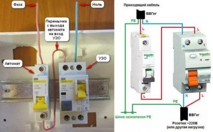
A logical conclusion follows from this: both circuit solutions are applicable in the practice of power supply to a home. Moreover, the optimal option seems to be the joint use of these two circuit solutions.
If an RCD is installed on the power supply line, the organization of grounding, by and large, can be eliminated. At the same time, the introduction of a protective device seems to be a reasonable solution for a two-wire electrical network, where there is technically no grounding bus.
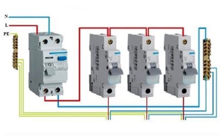
Actually, if you examine it carefully yourself RCD device, it will not be possible to find terminals on it specifically designed for connecting the “ground”.
This factor once again confirms the possibility of switching on without grounding. However, modern house-building projects necessarily require the presence of a grounding bus.
How does a protective device function without a ground?
The connection option without grounding is a typical case for apartments and private houses in old buildings. The power supply of such buildings, as a rule, is organized without the supply of a grounding bus. But how correct should one expect the RCD to operate without turning on the ground?
For example, during the operation of electrical equipment, a breakdown occurred on the housing. If there is no grounding bus, count on instantaneous operation installed RCD no need to. If a person touches the body of the broken equipment, the leakage current will flow to the “ground” through the person’s body.
It will take some period of time (device setting threshold) until the RCD trips. During this period of time (quite short), the risk of injury from exposure to electric current remains quite acceptable. Meanwhile, the RCD would operate immediately if there was a grounding bus.
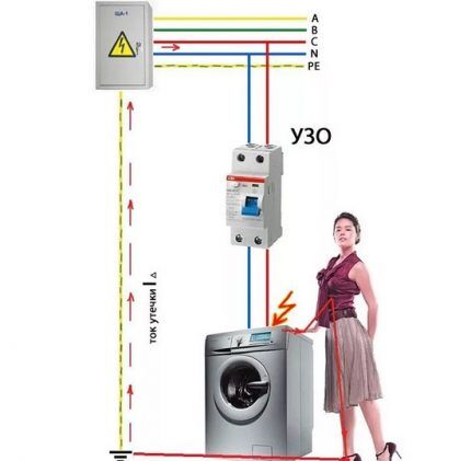
Using this example, it is easy to draw a conclusion about what to connect RCDs and automatic machines in the apartment panel or the panel of a private house should always be connected to the grounding bus. Another question is that there remain a sufficient number of buildings where it is not possible to do this due to the lack of “land” in the project schemes.
For buildings where the power supply is organized without grounding, the device of switching protection through an RCD actually appears to be the only effective means of protection that can be used in such conditions. Therefore, we will consider possible schemes applicable to power supply for private housing.
RCD connection diagrams without grounding
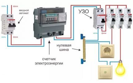
One of the traditional circuit solutions where an RCD protective device is used is the option of installing the device directly at the power supply input to the structure of the facility. That is, the residual current device is installed immediately after the electricity meter.
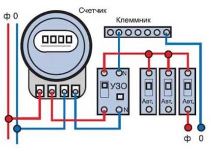
This approach ensures complete protection of the electrical wiring of the home, which means that the current leakage of any household electrical appliance is controlled. From the electrical network, voltage is supplied by cable to a device that combines two phase and two neutral terminals in one housing (there are also three-phase devices).
These two pairs of terminals are divided into input and output. A phase line passes through one pair, and a zero line through the other. Having completed the wiring according to this scheme, then additional machines are installed for each type of load.
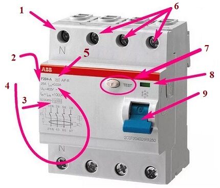
The advantageous aspect of this circuit design is the savings on electrical equipment. Just by installing one device, the issue of protection is successfully resolved. However, on the other hand, if a current leakage object appears in the home network, a complete blackout occurs in the home.
For some cases, this situation may not be suitable. To some extent, the comfort component for property owners is reduced. This drawback can be resolved using another circuit solution - more functional in terms of section-by-section shutdown.
Switching on an RCD with extended functionality
A slightly different circuit solution, suggesting implementation of RCD for each individual power supply branch, allows you to make the protection “softer” in relation to power blocking.
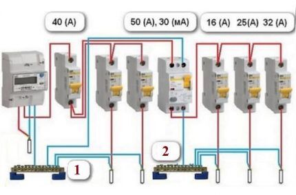
Several protection devices are used here, depending on the number of branches of the residential electrical network.
For example, if there are two branches, the diagram will look like this:
- Installation of one RCD is similar to the first option - at the entrance.
- Installation of subsequent RCDs after selectively installed machines network branches.
- On each branch line there is protection according to the number of consumers.
With this design of the circuit, control and voltage cut-off are carried out in relation to a separate branch of the home wiring. Therefore, the fact of a current leak detected on a separate line will lead to blocking only the section of the network where the broken load is connected. The remaining areas will remain in working order.
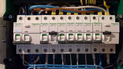
But a more functional solution does not come without certain drawbacks. It is clear that with an increase in the number of devices it will be necessary to expand switchboard. Increasing the size of the distribution board can also become a problem for the user. In addition, from the financial side, the choice of using the noted scheme also seems not entirely successful.
The costs will be almost double the increase compared to the first option. However, if you are already thinking about effective, full-featured protection, it is not recommended to save money.
The nuances of connection in private households
Private buildings differ significantly from municipal housing apartments. First of all, by using equipment that is never used in apartments. For example, traditional equipment for private households is electric heating systems or an electric heating module for a bath.
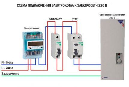
For any of such systems, it is necessary to install a protective shutdown, since these are not just household appliances, but quite powerful technological equipment. Here, the RCD is not just protection against current leakage to the housing, but also serves as a fire protection device.
In relation to such projects, a circuit solution based on the “TT” system is often used, which provides relative safety in cases of current leakage onto the equipment frame.
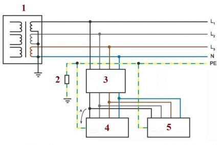
Supplementing such a circuit with a safety interlock device helps to increase the degree of reliability. However, the TT system requires a grounding bus.
Step-by-step instructions for implementing protection
For complete information regarding the connection of devices that provide protective cutoff, we will consider step by step the process of creating a communication circuit with the introduction of a protection device:
- Lead to electrical panel power cable from the centralized interface for introducing energy into the house.
- Mount a circuit breaker inside the switchboard (this device is pre-calculated to cut off the total network load).
- Mount the electric meter in a convenient place and connect the output of the machine to the input terminals of the meter.
- Install an RCD inside the panel and connect the input of the device (upper terminals) to the output terminals of the electric meter.
- Connect the phase conductor of the home electrical wiring to the output (phase) terminal of the RCD.
- Connect the neutral conductor of the home electrical wiring to the output (zero) terminal of the RCD.
- Connect the main cable to the terminals of the input circuit breaker.
When performing the above operations, you should take into account some nuances. For example, it is necessary to follow the rule of sequential connection of a circuit breaker with a protective cut-off device.
If it is not planned to introduce a machine into the network, it is necessary to install fuses instead of the machine.
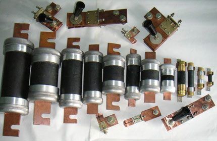
As a rule, it is recommended to take the rated current of the protective module slightly higher than the current value of the circuit breaker. In some cases, this parameter can be selected equal to the parameters of the machine.
When carrying out work to include a protective device in the power supply network, it is recommended to check all accessible circuits for possible defects. After installing the device, be sure to check the effectiveness of the cut-off. For this operation there is a special test key on the front panel of the device.
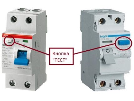
During installation, all connection work must be carried out carefully.
The network lines must be connected in strict accordance with the markings on the device body. That is, the phase is connected to the “phase” and, accordingly, the zero is connected to the “zero”. Changing the positions of the “components” poses a high risk of failure of the protective device.
Conclusions and useful video on the topic
This video concludes the article about devices used as protective systems for electrical networks, equipment and users of apartments and private houses. Review material with all the subtleties of use, which will certainly be useful for practice.
Connecting an RCD without grounding in modern apartments is not only not recommended, but also prohibited. If there is a need to install equipment in the electrical panel, be sure to contact the foreman who maintains the house. All work regarding filling the general apartment panel must be performed by a qualified specialist.
Describe how you connected a residual current device to interrupt the power supply in the event of a hazardous situation. It is possible that your advice will be very useful to site visitors. Please leave comments in the block below, post photos, ask questions.


There was a situation recently. My brother and I went to work part-time, but had to live, as always in such situations, in a trailer. So, we were told to completely connect all the wiring ourselves and throw an RCD to it, and also throw it ourselves to the distribution panel. Well, everything was done, but the grounding system had to be made from a steel rod driven into the ground. We then installed the meter ourselves. So, there is nothing particularly complicated here.
Good afternoon, Alexander. Assembling the shield and hammering in the ground electrode is really not difficult. Difficulties include calculations of wire cross-sections, the required number of grounding conductors, grounding conductors, selection of automatic devices, and RCDs.
It will come as a surprise to you, I think, that a single hammered rod may not be enough. The reason is trivial - it will not provide a “smooth” decrease in potential when a short circuit current flows through it. The consequences are the defeat of a person located near your pin by “step voltage”. I have attached a picture explaining the essence of the question.
By the way, the grounding you have constructed is subject to testing - if the resistance to current flow is greater than the standard, the device is dangerous. The PUE devotes ten pages to grounding - read Chapter 1.7.