How to check the RCD for operability: methods for checking technical condition
A residual current device (RCD) can confidently be considered one of the devices that should be in every home.Such a device is capable of signaling a current leak and, accordingly, saving residents from fire and electrical injuries.
However, in order to be completely confident in the protection, it is advisable to be aware of how to independently check the RCD and make sure that it is working properly.
In this material we will tell you what an RCD is, give the main characteristics of this device, and also name several simple ways to check the device’s functionality.
The content of the article:
What is an RCD?
The correct name of the RCD is an automatic circuit breaker controlled by differential current. This switching device serves to automatically interrupt the circuit when the unbalance current that occurs under certain conditions exceeds the established figures.
The operation of the internal mechanism of the device is based on the following rules: neutral and phase conductors are connected to the terminals, after which they are compared by current. In the normal state of the entire system, there is no difference between the phase current indicators and the neutral conductor data.Its appearance indicates a leak. Having analyzed the abnormal condition, the device turns off.
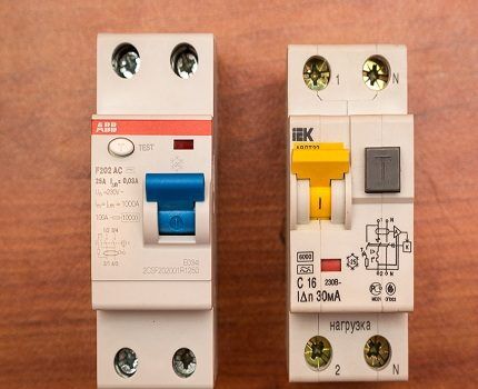
To put it in simpler terms, the RCD is triggered and breaks the network when the current begins to flow beyond the electrical wiring or devices connected to the electrical network.
In those circuits in which leaks are possible and the possibility of electric shock to people is very likely install RCD. In a house or apartment, these are places where vapors accumulate, thereby causing increased humidity. This is the kitchen and bathroom. In addition, these rooms are the most saturated with various types of electrical appliances.
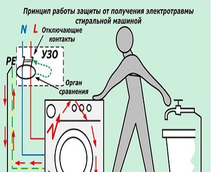
One of the usual electrical assistants can give a person an electric shock when it is not possible to ground it or this was not taken into account during the design. When the insulation of the leading wires in one of the devices is broken, current will flow to the body of the unit.
If there is no grounding, a person will receive an electric shock when touching such a surface. To prevent this from happening, it is necessary to install a protective shutdown device.
RCD designs may differ in their mode of action. Manufacturers produce devices that have an auxiliary power source for normal operation of the electronic circuit and devices that do without it.
Electromechanical protective devices are triggered directly by leakage current, using the potential of a pre-charged mechanical spring. The operation of RCDs on electronic components is entirely dependent on the presence of voltage in the network. It requires additional power to turn off. In this regard, the latter device is considered less reliable.
Characteristics of the protective device
You can find many different models of residual current switches on sale. They differ from each other in production standards, installation method and area of use.
The wrong choice of protection device can lead to the following troubles:
- The device will constantly operate in response to the slightest leaks that are present in the electrical network of each home.
- If a device with overrated characteristics was selected during purchase, it may not respond to an emergency situation. As a result, there is a high risk of electrical injury.
To avoid such incidents, it is imperative to study RCD characteristics. You can read them by special markings on the body of the device.
Rated load current
This is one of the most important characteristics. The number indicates the maximum current value that can pass through the device for a long time without causing any harm to it. The magnitude is determined by the immunity of power contacts and conductors of a certain load. However, they remain in working order.
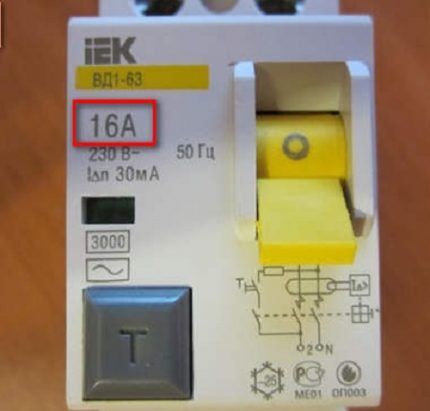
Rated current values are typical for all models: 16 A, 25 A, 40 A, 63 A, 80 A, 100 A, 125 A.
What is trip current?
We can say that this is the most important parameter. It indicates the leakage current at which the protection is triggered and the device is turned off. On the body this value is indicated by the symbols IΔn. Standard residual current rating settings range from 6 mA to 500 mA.
Each of the values indicates exactly where the device can be used. For example, a device with IΔn equal to 500 mA will not be able to protect a person from electrical injury.
Non-breaking rated residual current
This is a parameter characterizing the response threshold of the device. It is designated as IΔn0. The value is always equal to half of the rated differential current (IΔn), that is, a device with a value of 10 mA will be switched off during a current leak of 5 mA.
If a leakage current less than this indicator flows through the protective device, the device will not operate.
RCD response time
This value shows the reaction speed of the protective device in an emergency situation. The nominal tripping time of the RCD is indicated by the symbols Tn. The norm is a maximum of 0.3 seconds. High-quality modern protection devices operate in 0.1 seconds, but such a high speed is not in demand.
Types of devices: AC - the device is triggered when an alternating current occurs instantly; A – with alternating or pulsating current; B – at constant, rectified and alternating; S – a certain time is maintained before triggering (0.15-0.5 sec); G – exposure time is less than the previous one (0.06-0.08 sec).
Reasons for device operation
There are a lot of reasons for a network shutdown by a protection device, but only after identifying them can the problem be completely eliminated.
Moreover, you need to try to find the problem area as soon as possible in order to avoid serious consequences.
Reason #1 - current leakage
Network leaks most often occur when there is old electrical wiring. Over time, the insulation dries out and some areas become exposed. The same problem can arise after replacing the old wiring with a new one, when the connection was made poorly.

The third, quite common reason is accidental damage to hidden wiring. For example, driving a nail into a wall.
Reason #2 - short circuit between ground and zero
The PUE rules prohibit combining neutral conductors and grounding. However, some careless craftsmen reject the existing “taboos” and do everything their own way, despite the fact that in this way the threat of electrocution to people increases many times over.
Reason #3 - unfavorable weather conditions
Weather can significantly affect the performance of the protective device when the distribution panel is located outside the premises, that is, on the street. Due to the appearance of tiny water particles inside the structure, the device may trigger.
If it is frosty outside, the protection device, on the contrary, may not perform its functions. This is due to the fact that low temperatures negatively affect microcircuits and can completely damage them.
There are known cases of network shutdown by a protective device during a thunderstorm.Lightning can aggravate even very minor leaks present in a home.
Reason #4 - incorrect installation of the device itself
An incident such as a false shutdown can occur periodically due to improper installation of the protective device.
Therefore, it is advisable to carry out installation yourself only after thoroughly studying the instructions. This also includes incorrect selection of characteristics when purchasing.
Reason #5 - problems with household electrical appliances
Failure of the cord with which a household electrical appliance is connected to the network causes an instantaneous operation of the protective device.
This also happens when current leaks from internal spare parts, for example, the heating element of a water heater or the motor winding of any of the switched-on devices.
Reason #6 - high humidity
It happens that after installing hidden wiring, the route is covered with putty and they immediately try to check the work done. In such cases, the protective device is triggered due to the wet putty surrounding the wires.
This is due to the ability of water to provoke leakage through microscopic cracks and other insulation defects. If you wait until the putty material has completely dried and repeat the manipulation, most likely the shutdown will not happen again.
Checking the RCD for functionality
To feel safe, you should regularly, at least once a month, check the protective device.
You can do this yourself at home. All known verification methods are quite simple and accessible.
Method No. 1 - test using the TEST button
The testing button is located on the front panel of the device and is marked with the letter “T”.When it is pressed, a leak is simulated and protective mechanisms are activated. As a result, the device cuts power.
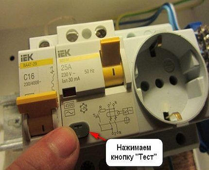
However, under certain conditions the RCD may not work:
- Incorrect device connection. A thorough study of the instructions and reconnecting the device according to all the rules will help correct the situation.
- The TEST button itself is faulty, that is, the device operates normally, but leakage simulation does not occur. In this case, even if installed correctly, the RCD will not respond to testing.
- Malfunctions in automation.
The last two versions can only be confirmed using alternative verification methods.
To ensure that the test mechanism operates reliably, you should repeat pressing the button 5-6 times. In this case, after each network shutdown, you must remember to return the control key to its original position (the “On” state).
Method number 2 - battery test
The second simple way that you can test the RCD yourself at home for functionality is to use a familiar AA battery.
Such testing can only be carried out with a protection device rated from 10 to 30 mA. If the device is designed for 100-300 mA, the RCD will not trip.
Using this technique, perform the following steps:
- Wiring is connected to each pole of a 1.5 - 9 Volt battery.
- One wire is connected to the input of the phase, the other to its output.
As a result of these manipulations, a working RCD will turn off. The same should happen if a battery is connected to the zero input and output.
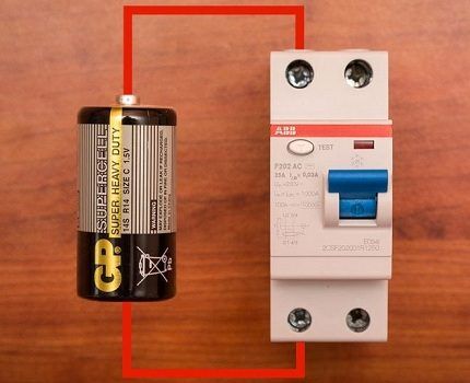
Before carrying out such an audit, it is imperative to study the characteristics of the device. If the device is marked A, it can be tested with a battery of any polarity. When checking the AC protective device, the device will respond only in one case. Therefore, if no operation occurs during the test, the polarity of the contacts should be changed.
Method number 3 - using an incandescent light bulb
Another surefire way to monitor the functionality of a protective device is with a light bulb.
To complete it you will need:
- a piece of electrical wire;
- incandescent lamp;
- cartridge;
- resistor;
- screwdrivers;
- insulating tape.
In addition to the items listed, a tool that can be used to easily remove the insulation may be useful. You can read about the best wire strippers in this material.
Incandescent lamps and resistors planned for testing must have suitable characteristics, because the RCD reacts to certain numbers. Most often, a protective device that is purchased for installation in a house or apartment is designed to respond to a leak of 30 mA.
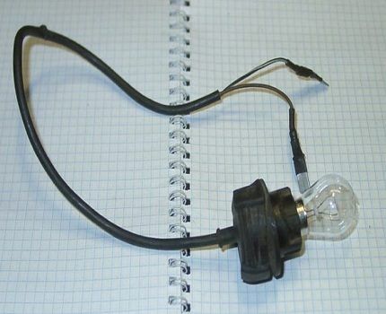
The required resistance is calculated using the formula:
R = U/I,
where U is the network voltage, and I is the differential current for which the RCD is designed (in this case it is 30 mA). The result is: 230/0.03 = 7700 Ohm.
A 10 W incandescent lamp has a resistance of approximately 5350 ohms. To get the desired figure, all that remains is to add another 2350 Ohms. It is with this value that a resistor is needed in this circuit.
After selecting the required elements, assemble the circuit and, performing the following manipulations, check the functionality of the RCD:
- One end of the wire is inserted into the socket phase.
- The other end is applied to the ground terminal in the same outlet.
During normal operation of the protective device, it is knocked out.
If there is no grounding in the house, the testing method changes slightly. On the input panel, namely in the place where the automation is located, insert the wire into the zero input terminal (marked N and located at the top). Its second end is inserted into the phase output terminal (marked L and located at the bottom). If everything is fine with the RCD, it will work.
Method No. 4 - checking with a tester
The method of checking the serviceability of a protection device using special ammeter or multimeter devices is also used at home.
To complete it you will need:
- light bulb (10 W);
- rheostat;
- resistor (2 kOhm);
- wires.
Instead of a rheostat for testing, you can use Dimmer. It is endowed with a similar operating principle.
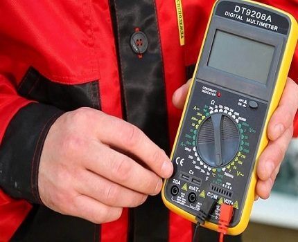
The circuit is assembled in the following sequence: ammeter - light bulb - resistor - rheostat. The ammeter probe is connected to the zero input in the protective device, and the wire is connected from the rheostat to the phase output.
Next, slowly turn the rheostat regulator in the direction of increasing current leakage. When the protection device is triggered, the ammeter will record the leakage current.
Conclusions and useful video on the topic
Checking the RCD for activation using simple improvised means:
From this video you can learn how to test an RCD using a battery:
Having studied the recommendations in detail, you can choose the best option for yourself and regularly carry out monitoring yourself. Only in this case can you be completely sure that no one in the household will be injured by electric shock.
If you have questions about the topic of the article, you can ask them in the comments section. Maybe you know other ways to check the RCD for functionality? Tell our readers about them.


Well, not every person has a tester device at home, and buying it specifically to use it and test it once is stupid. Therefore, the first three verification methods will be more relevant. I didn’t have to use a battery, I didn’t know about this option, but using an incandescent lamp it’s quite possible to check it yourself, there’s nothing complicated there. Everything is clear with the test button; usually it is marked in orange.
Good day, Sergey. Of course, the methods disclosed in the article are useful. True, in these ways it is found out “whether the RCD is triggered at all.” Agree, even the tester does not record the time of occurrence of a harmful current and the time of breaking the circuit by the RCD contacts. Only by recording this period of time can one judge the usefulness of the protective function.
For example, the Krasnodar Electrical Laboratory uses the PZO 500 device, which even detects the initial phase of the occurrence of “dangerous current”.The “harmful current” is generated by a microprocessor - it ensures a smooth increase, records the current that should cause a shutdown, and records the response time. To make the complexity of the check clear, I have attached a screenshot of the Instructions page.
Regarding the frequency of testing, the PUE recommends following the operating documentation of the device. RCD tests are usually combined with tests of the corresponding network. Checking with the “Test” button is assigned to operational personnel – the “monthly test” is often mentioned here.