Electrical wiring diagrams in a private house: rules and design errors + nuances of electrical wiring
The electrical supply diagram of a private home is a lot of organized cables, wires, and protective devices. The correct selection of parameters and characteristics of the circuit elements guarantees the safety and comfort of property owners.
If the circuit is drawn up correctly, taking into account the requirements of the PUE and other regulatory documents, there is nothing to fear - there will always be light and warmth in the rooms, and electrical appliances will not break due to power surges or short circuits in the network. Therefore, special attention should be paid to electrical design.
We suggest you understand all the intricacies of this process. The article outlines the general requirements for designing an electrical network, provides practical advice on choosing wires, and also discusses in detail typical electrical wiring diagrams.
In addition, we have prepared a review of common mistakes, taking into account which will help to avoid shortcomings in the development and installation of power supply networks.
The content of the article:
General rules for electrical network design
When there were few electrical appliances, and several 40-60 W light bulbs were enough for lighting, a primitive circuit was drawn up to set up the power supply system, including several switches and sockets.
Now, with the advent of a large number of energy-dependent household appliances, the circuit is necessarily differentiated into group lines protected by circuit breakers and other devices.
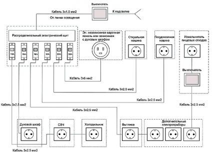
If you think through all the nuances of the location of electrical wiring in a private house, taking into account the use of copper wire, it will last at least 20 years. Typically, a diagram is drawn up along with the design of a new house or before a major renovation.
You should start by indicating the installation locations of such elements as:
- sockets;
- switches;
- distribution boxes;
- lighting devices;
- powerful household appliances;
- electrical panel
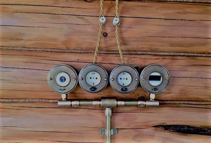
At the same stage, you should decide on the method of laying the cables - open or closed. In houses with plastered walls, a closed method is usually used; in houses with wooden walls, an open method is used.
Whatever scheme you use, there are a number of rules that you cannot deviate from. They are prescribed in regulatory documentation, and their effectiveness has been proven for decades.
Here are a few important axioms of electrical installation that will be required to draw up a diagram:
In addition to the rules, personal comfort should also be taken into account. For example, a double bed usually has two sockets installed - one on each side.
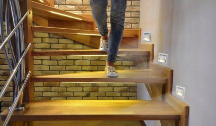
Switches are located at a height of 80-90 cm from the floor. In large halls, corridors, rooms install pass-through switches.
Be sure to ground all metal outlets and objects connected to power lines. For grounding in electrical installations, the third core of the cable is used - a wire in yellow-green insulation.
Recommendations for choosing wires
In houses made of brick, aerated concrete blocks, and cinder blocks, interior wall decoration is required, which means that a hidden method is used for laying wires.
To provide additional protection, and in case of repair to quickly replace the cable, it is placed in corrugated sleeve non-flammable polymer.
To get it right select the wire cross-section, specialists make calculations related to determining the load.
However, based on standard diagrams and many years of experience, qualified electricians adhere to the following parameters:
- lighting circuits – 3*1.5 mm² or 3*2 mm²;
- socket groups – 3*2.5 mm²;
- electric stove/oven – 3*4 mm²;
- air conditioner – 3*2.5 mm², for devices more powerful than 5 kW – 3*4 mm²;
- heating boilers – 3*4 mm² or more (according to the manufacturer’s recommendations).
The optimal type of cable is three-core copper: VVGng, ShVVPng. It is impossible to use wires with a cross-section smaller than the specified one, as they will not match the load and will begin to melt, creating a dangerous situation.
Analysis of electrical wiring diagrams
Let's look at several typical schemes that are used during construction or major repairs. All options are united by the presence of a protective group: dividing the electrical wiring into circuits, each of which is connected to a separate circuit breaker.
Option #1 – general plan for the whole house
This is not a wiring diagram, but a listing of all electrical devices that are planned to be located in the house. Using it you can calculate how many machines you will need and RCD, count the total number of power lines leading to the switchboard.
Here you should indicate the type of power supply network in order to select the correct cable. For a 3-phase network, use a 5-wire cable, for a 1-phase network, use a 3-wire cable.
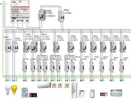
The electrical panel is located in a separate room inside the house, in the hallway, or in the nearby garage. Voltage stabilizers and a backup generator are also installed there, which supplies the house with electricity during periods when the centralized line is disconnected.
For ease of maintenance of a two- or three-story mansion, each floor also installing an electrical panel. All distribution boards are connected to an input cable - copper wire with a cross-section of 15-35 mm².
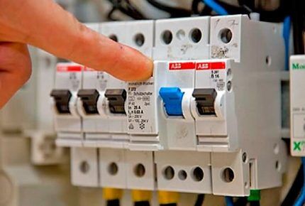
If you plan to place several lamps and sockets in a separate room, then you need to install junction box. It connects the input cable to the lighting line and socket group.
Option #2 – sample wiring diagram
To draw a wiring diagram, you need to take a house plan and mark on it where electrical devices will be installed.
This document becomes the basis for drawing up an estimate - it is easy to use it to count not only the number of switches, sockets and additional materials, but also to calculate the footage of wires.
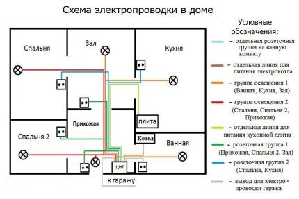
The point of entry of the power line into the house and the installation location of the electrical panel must be indicated. Then, on separate lines, distribution boxes, electrical installations, and lighting fixtures should be noted.
High power devices also need to be labeled as they are powered by individual lines.
If outbuildings are connected to the building - a bathhouse, a garage, a workshop - this should also be reflected in the diagram, since it is part of the electrical wiring in a particular private house.
There are no special symbols for hand-drawn diagrams; the main thing is that the home owner and installers understand what lies behind each symbol. However, it is better to use common designations for electrical circuitsso that you can understand the project yourself later.
Option #3 – technical solution for a small house
All plans and diagrams are similar, since they are built on the same principle, but they may differ in the number of installed sockets and lighting circuits, and, consequently, in the number of protective devices connected to them.
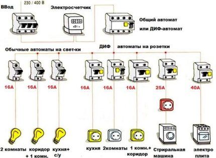
An input switch is installed in front of the network, which, if necessary, can be used to de-energize the entire house and turn off the electricity meter. Then comes the counter, and after that comes the protective groups.
For powerful units, such as a heating boiler or a washing machine, 25-40 A machines are installed. The wire cross-section should also be increased to 3.5-5 mm².
Using such a diagram, it is not possible to calculate the footage of wires, but the number of sockets, distribution boxes, switches, RCDs, and automatic circuit breakers is easy to calculate.
Option #4 – electrical circuit for the basement/garage
Often, the basement of a private house becomes a utility room where a washing machine is installed and a dryer is equipped, a cellar for storing crops, or even a warm garage. It is much more convenient when such a room is fully equipped with sockets and lamps.
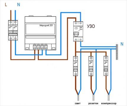
If you do not take into account the meter, the electrical panel will remain with input circuit breakers, a grounding bus, a 20 A RCD, three circuit breakers: on the lighting line, for sockets and for the compressor.Additional powerful equipment also requires automatic protection.
Option #5 – principles of kitchen wiring
Scheme electricians for the kitchen in a private house is practically no different from a similar scheme for a city apartment.
Its peculiarity is a large number of connected electrical appliances, therefore, it will be necessary to allocate several power lines with separate circuit breakers.
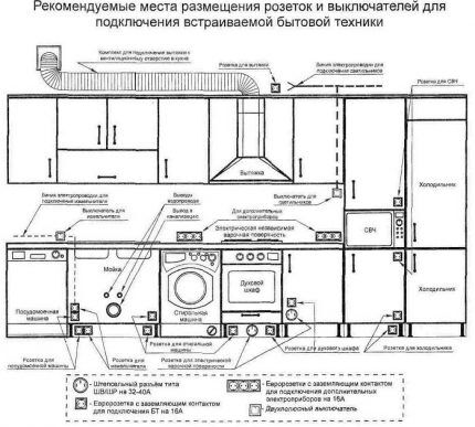
When drawing up a vertically oriented diagram, it is necessary to display on paper a furniture set with the arrangement of all equipment.
Socketless connections, for example, at an oven, are made under the countertop, near the wall, while sockets for a toaster, electric kettle, multicooker, and food processor are better placed above the work table.
Small household appliances are easier to unplug if the electrical installation device is at hand. Sockets installed near the sink must have degree of protection from IP44 or higher.
Review of common design mistakes
Defects in the design or planning of work entail installation errors, and this threatens disruptions in the functioning of the electrical network. The result may be the failure of expensive equipment, and even worse, an electrical injury to one of the residents.
What mistakes should you avoid:
- use low-quality products without labeling and certification;
- make one-to-one calculations - any technical products and materials must be purchased with a reserve;
- include in the project the installation of conventional sockets for connecting hobs, boilers, heat guns;
- in wooden houses plan the use of closed wiring - more complex and subject to the list of requirements of the PUE;
- design switching of low-voltage and high-power power wires in one distribution box;
- plan to connect wires using twists that are dangerous for further maintenance and operation; the best option is ready-made terminals;
- make circuits from aluminum and copper wires, and also use aluminum wiring.
Some errors relate to incorrect calculations. For example, grooves under the cable with a closed installation method should be laid to a depth of 2-2.5 cm, no less.
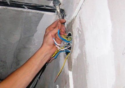
You cannot connect the grounding of sockets using a cable, or ground them on cast iron sewer or steel gas pipes.
If you do not know how to properly install electrical wiring in your home, contact the design organization. Specialists will visit the site and draw up a wiring diagram based on specific installation conditions.
Conclusions and useful video on the topic
Analysis of the floor plan:
Rules for drawing up electrical wiring diagrams:
Description of the device diagram on the distribution board:
Responsibility and risks for “independent activities” when drawing up a project fall on the shoulders of the home owner. If you do not have the appropriate education and experience, we recommend ordering documents from an organization that is engaged in professional development of power supply projects.
Do you have personal experience in designing and installing electrical wiring in a private home? Do you want to share your accumulated knowledge or ask questions on the topic? Please leave comments and participate in discussions - the feedback form is located below.


An extensive electrical wiring system, especially one laid in a hidden way behind a plasterboard partition, also has its disadvantages. The main one is that over time, a cable, even a well-fastened one, can sag. I believe that you should always use corrugated pipe when conducting electrical wiring and be sure to photograph the electrical work. You also need to make diagrams for residents of an apartment or house. If you forget about this, then when you try to nail a nail, you can get an electric shock.
Anton, well, no one is saying that the pipe is prohibited from being used, or that residents should not be given diagrams. This is clearly a far-fetched minus. The cable is unlikely to simply sag, except over a very long time frame. But the pipe will not save you from electric shock, but I am sure that in any case the resident will have a diagram, otherwise it simply makes no sense. And this method will also have few alternatives.
The author decided to ruin the readers? Why drag a 21A conductive wire to a 16A socket? Why is there more than 1 sq. wire for lighting devices? mm? Where have you come across a washing machine with more power than 2 kW in everyday life and why would you need a 25A machine in this case?
Good afternoon, Vitaly.
I will take an intermediate position between the author and you.
The question of how much to “carry” for lighting fixtures and other loads is decided by the design.In modern multi-storey cottages, a “lighting device” can concentrate a significant load - with ordinary apartments, of course, there are no questions.
Sometimes the author's terminology is confusing. For example, “lighting circuits – 3*1.5 mm² or 3*2 mm²;”. After thinking about it, I realized that the main lines were meant - so as not to waste words, I attached an explanatory diagram below. Agree, highways can have impressive cross-sections.
About a 16-amp outlet and a 21-amp wire - this can also happen. For example, the customer asked for reserve squares in order to later expand the set of electrical appliances.
Regarding the power of washing machines. For example, some Samsung charge more than 2 kW.
Vitaly, are you familiar with the PUE? It clearly states the minimum requirements for intra-apartment wiring, in particular for the cross-section of conductor cores: lighting - at least 1.5 mm2, socket networks - 2.5 mm2. And it is these rules that electricians should follow.
Destruction is when a house burns down from a thin wire. And laying a cable for 16-amp consumers designed for 25-amp loads is a safety measure. It would be an unnecessary waste if you put a wire for 40-50 A or higher on a 16A socket.
Guys, I’ve been doing electrical work in apartments and houses for 20 years, I have a professional education and a 5th (advanced) category, but for the first time in my life I’m hearing about a wire with a cross-section of 2mm.sq. ))
Is there a fifth lower rank?..
This is just a typo, the person in a hurry forgot to press two keys “,” and “5” - this is obvious from the context.