Rules for connecting an RCD to a single-phase network without grounding: the best diagrams + work procedure
A single-phase electrical network is familiar to every household.Regardless of whether a private house or a municipal apartment is operated, users in any case actively consume electricity.
This type of energy, however, cannot be considered completely safe. Therefore, an urgent task seems to be connecting an RCD to a single-phase network without grounding - a special device that significantly increases the degree of safety when using electricity.
Let's look together at the most common schemes for connecting an RCD to a single-phase network, and also determine the procedure for carrying out the connection work.
The content of the article:
A general view of protective modules
Despite the construction of electrical wiring diagrams, carried out according to approved rules, the risk of electric shock always remains. Therefore, it is important to take care of safety in a timely manner.
Residual current device - this is how the abbreviation “UZO” is interpreted in technical language.
From the point of view of the design, it does not look the most complex among modern electrical equipment. Nevertheless, it performs the protection functions quite efficiently and reliably.
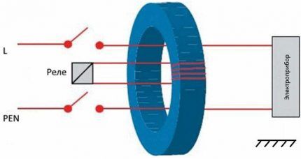
It should be noted that there are types of RCD, based on which a specific protective scheme is organized in each specific case:
- guaranteeing safety of touch;
- preventive technical damage;
- counteracting fire hazard.
Each device with specific functionality differs from other designs in operating parameters, in particular – rated current and cut-off current.
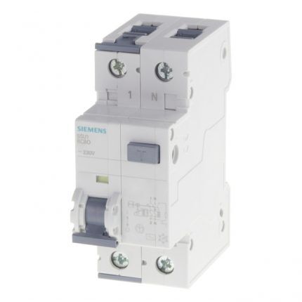
The most sensitive device, of course, is the RCD, designed to block the power source in case people unintentionally touch live parts of the circuits. The current cut-off range for such devices is in the range of 10-30 mA.
The best diagrams for connecting an RCD
For lines of electrical networks for household purposes, the introduction of RCDs without “ground” is typical. The main share of circuit solutions in the household sector is precisely single-phase wiring, where in principle there are only two lines: phase and zero.
Features of circuits without grounding
The schematic diagram of an electrical circuit without grounding must be carried out taking into account the inclusion of automatic protection for “short circuit” (short circuit) and overload current.
This is an obvious factor, because individual RCD devices are not designed to protect against such phenomena. These devices only protect against leakage currents.
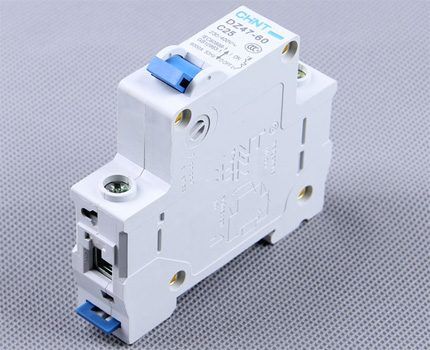
The range of cut-off currents and technical characteristics of circuit breakers are somewhat different from the operating parameters of protective RCDs.
Meanwhile, there are universal cut-off devices that combine in one device the functions of a circuit breaker and protection against unintentional contact with live electrical buses.
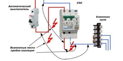
Each protective device structurally involves switching both conductors of the supply cable - phase and zero.
At the same time, when installing electrical wiring, you should accurately connect the conductors to the working terminals. Incorrect installation can result in damage to the protection device, which will lead to the inoperability of the protection system as a whole.
Classic inclusion option
Depending on the technical load (number of household appliances) and the number of rooms, an apartment or house can operate a single complete network or a network consisting of several subnets.
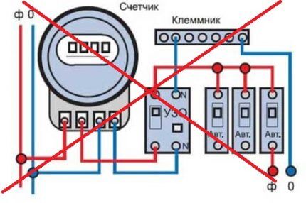
For the first case, one RCD device is usually sufficient to organize a protective shutdown. Based on the parameters of the current consumed or the total power consumed, in this case the protective device is selected according to the rated current and determined with the cut-off current.
For the second option, devices are implemented on each of the existing subnets. In this case, as a rule, all installed RCDs are supplemented with circuit breakers designed for the power consumption of a separate subnetwork.
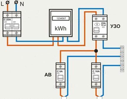
The classic design of the circuit diagram for switching on an RCD “without ground” is traditionally performed as follows:
- The main power cable, consisting of two cores (phase, zero), is supplied to the machine.
- From the circuit breaker, both wires are connected to the electric meter.
- Next, from the electric meter, two power wires are connected to the input terminals of the RCD.
After the protective device, for the option without subnets, there is no need to install a backup circuit breaker, but in some cases experts recommend doing this.
If a circuit with subnets is used, then after the RCD, a separate machine must be installed on each branch.
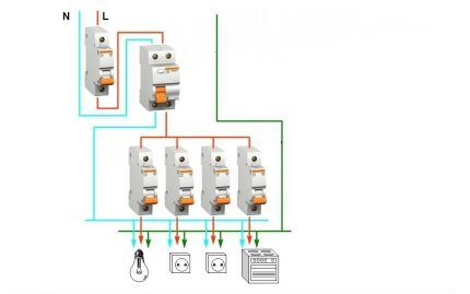
Thus, the phase conductor extending from the protection device supplies the working networks through additional circuit breakers.
The neutral core, which also passes through the cut-off device circuit, is brought out to a common zero bus, from where it is distributed along the zero tap lines for connecting the load.
Which RCD connection circuit is better?
Better or worse scheme - these concepts are purely superficial. How effective this or that scheme can be is the question.
And here even a non-specialist understands that a multi-stage option, where different levels of protection are used, seems more effective than any other simplified one.
Therefore, a power supply device diagram with subnets, when one common RCD and additional protection devices are used on each of the branches of the electrical circuit, clearly looks preferable.
The construction of such a circuit, as a rule, involves the installation of a main protective device with a cut-off current of 100-300 mA. And additional devices distributed over separate branches of the common circuit have a cutoff current of no higher than 30 mA.
In this way, double protection is provided - fire protection and in case of unintentional contact.
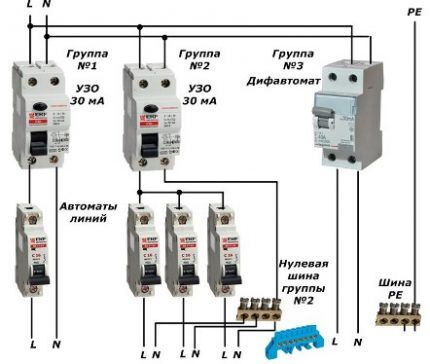
The advantages of building a power network in this way are also manifested in the fact that in the event of an alarm, only a separate section of household electrical wiring is usually turned off, and not the general power zone. Under such shutdown conditions, detecting the location of the current leak is much easier.
On the other hand, the so-called extended circuit for switching on an RCD without grounding is burdensome for the user, from the point of view of increasing construction costs.
It is clear that in order to build multi-stage protection, in this case more significant financial investments will be required than for the installation of a simplified version.
Scheme for using an RCD in a private house
Municipal buildings usually do not pose any special problems with security functions, with the exception of frankly old buildings.
Networks of council houses are usually serviced by a service. But in a private home, owners often have to resolve such issues on their own.
True, amateur performance in such matters is not recommended. And if you need to organize a reliable connection diagram using an RCD, you should contact energy specialists.
Private housing projects, especially modern buildings, are characterized by fairly complex energy supply protection schemes.
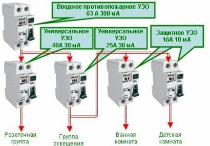
Let's consider one of them for a device in a private home:
- A total of 5 protective devices are used with a cut-off current range from 10 to 300 mA.
- The main protection against short circuit and possible fire is a 300 mA RCD.
- Two universal 30 mA devices are used for lighting and a socket group.
- Highly sensitive 10 mA devices are installed on the power supply lines of rooms with an aggressive environment and where increased protection is required.
- The general circuit is divided into subnets depending on the purpose.
The functionality of such a scheme can be described as follows. The first device, a 300 mA RCD, performs the functions of a fire safety interlock.
At the same time, this device is characterized by a cutoff based on the total leakage current from all subnetworks, if this value exceeds the permissible parameter.
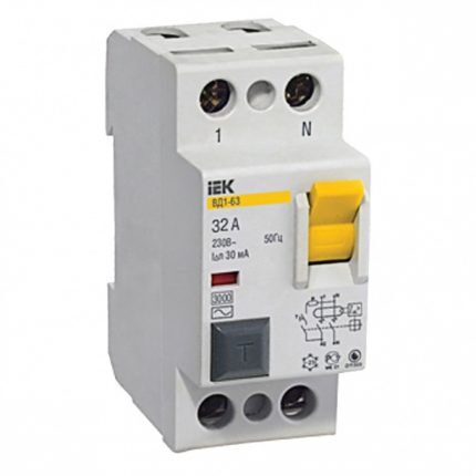
Following the fire protection system, a universal system is activated, which guarantees operation in the event of detection of a short circuit and current leaks over 30 mA.
The serviced area for the RCD of this subnetwork is the line supplying the lighting devices and the socket group.
Finally, a kind of third protective stage is formed by highly sensitive 10 mA devices, which in fact serve areas where conditions require an extraordinary approach - a bathroom, a children's room.
Protection option for dacha farming
Modern projects of dacha farms are increasingly becoming a full-fledged construction infrastructure, in no way inferior to the residential sector for permanent residence. It is obvious that the factor of comprehensive protection is becoming relevant for country houses.
However, in relation to such farms, electrical safety requirements are, as a rule, somewhat lower than in the real residential sector.
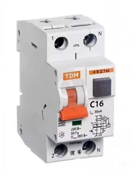
Therefore, simplified circuit solutions using universal RCDs with a cut-off current of 30 mA are traditionally used here.
This type of protective device provides quite effective protection in case of unintentional contact with electrical areas where current leakage is possible.
In addition, the same design of the devices provides blocking in case of technical damage to equipment or electrical wiring.
In addition to the RCD, country wiring is also equipped with circuit breakers - usually one each on the light line and the line of electrical sockets.
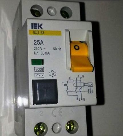
If the operation of additional equipment is required, it is connected to an existing circuit through an additional circuit breaker.
The procedure for connection work
First of all, care should be taken to comply with all required safety measures when performing this type of work.
Turn off the power supply at the installation site and provide the process with working tools.
Then you have to follow a number of rules when performing electrical installation work:
- Installation is carried out strictly according to the previously prepared scheme.
- The device is mounted inside the electrical panel next to the machines.
- The device fixed in the shield is connected to other components through conductors with a cross-section of at least 2.5 mm (copper). Important to use withconnection diagrams, printed on the body of the protective device.
- After completing the installation and wiring of conductors, check the correctness of the connections and supply power to the area.
- Check the operation of the device by activating the “Test” button.
As a rule, a correctly selected device successfully passes the test mode.
If this does not happen, the device did not work, which means that the calculations were performed incorrectly or there are some defects in the device circuit. Then the RCD should be replaced.
Conclusions and useful video on the topic
The video talks about the nuances and shows the details of connecting a protective device under operating conditions of electrical wiring made using the TN-C system.
The author's clear explanations about the operation of RCDs in such conditions and practical demonstrations:
To complete the review of possible circuit configurations with RCDs, it is necessary to note the relevance of the use of these devices. The introduction of residual current cut-off devices is a significant increase in the level of safety when using electrical networks. The main thing is to choose and connect the devices correctly.
If you have experience connecting RCDs to single-phase networks without grounding, please share it with our readers. Tell us what points you definitely need to pay attention to, perhaps you know some connection subtleties that we did not mention in our material? Leave your comments and ask questions in the block below the article.


Perhaps, according to the rules, it is necessary to use one of the above-described schemes in a private house, but in reality I have never seen anyone have a machine gun for each room. I live in a private house. I read the article and am amazed. Where should I plug in the machine for the bathroom? Or for a nursery? This probably means that there is a switchboard in the house. Has the author ever considered how much a penny like this would cost?
Believe me, it is much cheaper than rebuilding a burned down house.
Good afternoon, Igor.
Most likely, you built your house without any hassles with the designers, otherwise you would have been given a power supply diagram of the appropriate quality - with an input panel, a functionally separated group network. By the latter I mean separate lines running from the house panel to illuminate different rooms, to socket groups of rooms, etc.
This division of the apartment or cottage network is recommended by the PUE and other regulatory documents. All also provide for the installation of an RCD. Mandatory requirements are for municipal apartments. If something like this is laid down by “officials” for the sphere under their jurisdiction, then a private owner, who cares about himself more than the state, must at least adhere to the PUE.
About the high cost of “wiring” - for a two-story cottage of 120 square meters, the total cost of electrical equipment is slightly more than ₽100 thousand. The cost of such a house in the province does not exceed ₽4 million.
Screenshot of the text from SP 31-110-2003 – attached.