Forced ventilation in the cellar: rules and arrangement schemes
Basements and semi-basements serve different purposes. Previously, they housed vegetable storage facilities and communications.Nowadays, basements are assigned other functions, from garages to gyms and even offices.
In any case, forced ventilation in the cellar of a building is a justified need, dictated by the need for a systematic supply of fresh air to replace exhaust air. We suggest that you take a good look at this issue.
The content of the article:
- Each cellar has its own ventilation
- Moisture in basements
- Thermal insulation of pipes from condensate
- Calculation of air exchange in the basement
- Calculation of air exchange taking into account heat and moisture
- Calculation of air duct parameters
- Calculation of ventilation network resistance
- Selecting an Exhaust Fan
- Basement ventilation duct diagram
- Conclusions and useful video on the topic
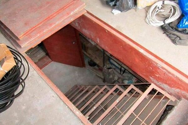
Each cellar has its own ventilation
For a buried vegetable storage facility located under a private house, forced, i.e. mechanical ventilation is not needed.
Fruit and vegetable products are stored better if air exchange in the basement is minimal. Therefore, simple vents and supply and exhaust ventilation ducts will be sufficient.

According to design standards for vegetable storage facilities NTP APK 1.10.12.001-02, ventilation, for example, of potatoes and root crops should occur in a volume of 50-70 m3/h per ton of vegetables. Moreover, in the winter months, the ventilation intensity should be halved so as not to freeze the root crops.
Those. ventilation during the cold season home cellar should be in the format of 0.3-0.5 room air volume per hour.
The need for forced ventilation in the cellar arises if the scheme with natural air flow does not work.However, it will also be necessary to eliminate sources of air humidification.
Moisture in basements
Musty air and humidity are common problems in basements. The first problem occurs due to insufficient air exchange. The basement is buried 2.5-2.8 m into the ground, its walls are made with maximum moisture and air tightness.
And natural ventilation, represented by vertical house ducts, is absent in many basements and cellars.
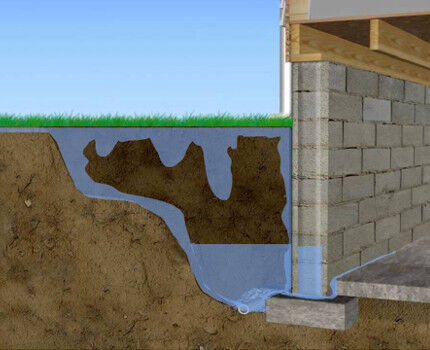
Significant air humidity in the basement is caused by poor waterproofing of the walls. The second reason is worn-out pipelines stretched through basement utility rooms. Moreover, condensate is deposited on them regardless of the integrity of the pipes and the tightness of the detachable connections.
The problem of excess moisture must be resolved before developing a project and building a basement ventilation system. It is necessary to restore or increase the degree of tightness of the cellar walls, seal the pipelines and cover them with insulation.
The last measure will eliminate the influence of condensate on the pipe material. Then the ventilation needs of the cellar are determined.
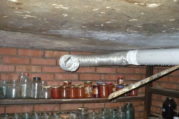
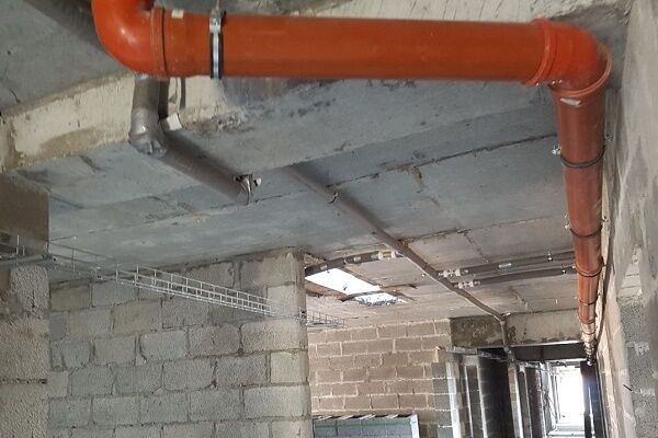
Thermal insulation of pipes from condensate
Drops of water appear only on the surface of household pipelines through which cold liquid flows (drinking water and sewage). Moisture present in the indoor atmosphere condenses on cold pipes due to the temperature difference between their surface and the air.
The colder the pipes, the more saturated the air is with moisture, the more active the process of water condensation occurs.

The temperature difference between the air and the surface of cold water supply pipes in private homes is usually small. After all, when households infrequently consume cold water, there is no movement of it through the pipes, so the temperatures of the home atmosphere and the pipeline are almost equalized.
But in a multi-storey building, residential or office, cold water is used almost continuously and the pipe is constantly cold.
The simplest way to combat condensation on pipes is to equalize the temperatures of the pipes and the atmosphere. It is necessary to cover the cold pipeline with steam and heat insulating material along its entire length.
Condensation collects on a cold pipe, regardless of what it is made of. Polymers, ferrous metals, cast iron or copper – it doesn’t matter. All “cold” communication pipes will have to be insulated!

A tubular heat insulator made of foamed LDPE will prevent contact of a cold pipe with air. The wall of the heat-insulating “tube” is at least 30 mm. The diameter of the tubular insulation is chosen slightly larger than that of the pipeline insulated from atmospheric humidity. It’s easy to put on the insulation – cut it to length, then cover the pipe with it.
Right after sealing the pipeline with a heat insulator it is necessary to wrap it on top with reinforced pipe tape.For maximum thermal insulation and greater attractiveness, wrapping with foil tape (aluminum) is carried out.
Shut-off valves and complexly curved sections of a cold pipeline that cannot be covered with tubular insulation are wrapped with tape in several layers.
Calculation of air exchange in the basement
Before you search for ventilation equipment and plan location of ventilation ducts in the basement, it is necessary to determine the air exchange needs. In a simplified format, i.e. Without taking into account the possible content of harmful substances in the atmosphere of the basement, the air exchange in it is calculated using the formula:
L=Vsub • KR
Wherein:
- L – estimated air exchange requirement, m3/h;
- Vsub – volume of the basement, m3;
- KR – minimum air exchange rate, 1/hour (see below).
The resulting air exchange value will allow you to determine the power characteristics of the basement forced ventilation system.

However, to calculate the formula, data on the air volume of the room and the air exchange rate are required.
The first parameter is calculated like this:
Vsub=A•B•H
Where:
- A – basement length;
- B – basement width;
- H – basement height.
To determine the volume of a room in cubic meters, the results of measurements of its width, length and height are converted into meters. For example, for a basement 5 m wide, 20 m long and 2.7 m high, the volume will be 5 • 20 • 2.7 = 270 m3.

For spacious basements, the minimum air exchange rate KR is determined based on the needs of one person for fresh (supply) air per hour. The table shows the standard human needs for air exchange depending on the use of a given room.
Air exchange can also be calculated by the number of people who will be (for example, working) in the basement:
L=Lpeople•Nl
Where:
- Lpeople – air exchange rate for one person, m3/h•person;
- Nl – estimated number of people in the basement.
The standards establish human needs at 20-25 m3/h of supply air with low physical activity, at 45 m3/h when performing simple physical work and at 60 m3/h during high physical activity.
Calculation of air exchange taking into account heat and moisture
If it is necessary to calculate air exchange, taking into account the elimination of excess heat, the formula is used:
L=Q/(p•Cр•(tat-tP))
Wherein:
- p – air density (at t 20 °C equals 1.205 kg/m3);
- CR – heat capacity of air (at t 20°C equals 1.005 kJ/(kg•K));
- Q – volume of heat released into the basement, kW;
- tat – temperature of air removed from the room, °C;
- tP – supply air temperature, °C.
The need to take into account the heat eliminated during ventilation is necessary to maintain a certain temperature balance in the basement atmosphere.

Simultaneously with the removal of air, the process of air exchange removes moisture released into it by various moisture-containing objects (including people). Formula for calculating air exchange taking into account moisture release:
L=D/((dat-dP)•p)
Wherein:
- D – amount of moisture released during air exchange, g/h;
- dat – moisture content in the removed air, g water/kg air;
- dP – moisture content in the supply air, g water/kg air;
- p – air density (at t 20OC is 1.205 kg/m3).
Air exchange, including the release of moisture, is calculated for objects with high humidity (for example, swimming pools). Also, the release of moisture is taken into account for basements visited by people for the purpose of physical exercise (for example, a gym).
Consistently high air humidity will significantly complicate the operation of forced ventilation in the basement. Ventilation will need to be supplemented with filters to collect condensed moisture.
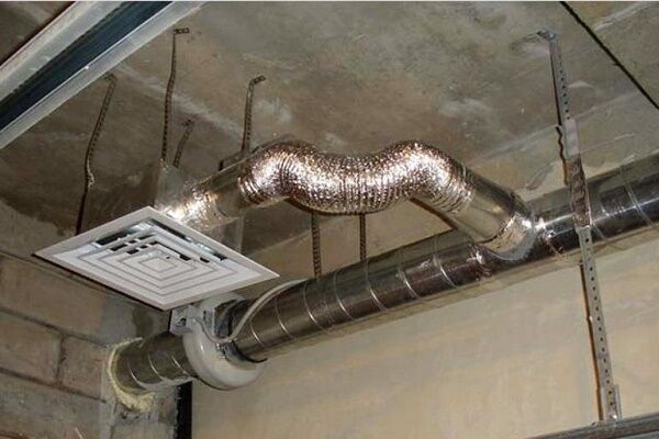
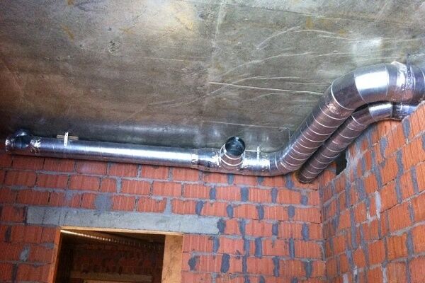
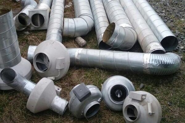
Calculation of air duct parameters
Having data on the ventilation air volume, we move on to determining the characteristics of the air ducts. One more parameter is needed - the speed of air pumping through the ventilation duct.
The faster the air flow, the less bulky air ducts can be used. But the system noise and network resistance will also increase. It is optimal to pump air at a speed of 3-4 m/s or less.

If the basement interior allows the use of round air ducts, it is more profitable to use them. In addition, a network of ventilation ducts from round air ducts is easier to assemble, because they are flexible.
Here is a formula that allows you to calculate the area of the duct according to its cross-section:
SSt.=L•2.778/V
Wherein:
- SSt. – calculated cross-sectional area of the ventilation duct (air duct), cm2;
- L – air flow when pumping through the air duct, m3/h;
- V – speed at which air moves through the air duct, m/s;
- 2.778 – the value of the coefficient that allows you to reconcile heterogeneous parameters in the formula (centimeters and meters, seconds and hours).
It is more convenient to calculate the cross-sectional area of the ventilation duct in cm2. In other units of measurement, this parameter of the ventilation system is difficult to perceive.

However, determining the estimated cross-sectional area of the ventilation duct will not allow you to correctly select the cross-section of the air ducts, since it does not take into account their shape.
Calculate required duct area using its cross-section can be obtained using the following formulas:
For round ducts:
S=3.14•D2/400
For rectangular ducts:
S=A•B /100
In these formulas:
- S – actual cross-sectional area of the ventilation duct, cm2;
- D – diameter of the round air duct, mm;
- 3.14 – value of the number π (pi);
- A and B – height and width of the rectangular duct, mm.
If there is only one air main channel, then the actual cross-sectional area is calculated only for it. If branches are made from the main highway, then this parameter is calculated for each “branch” separately.
Calculation of ventilation network resistance
The higher air speed in the ventilation duct, the higher the resistance to the movement of air masses in the ventilation complex. This unpleasant phenomenon is called “loss of pressure.”

The ventilation unit must develop an air pressure sufficient to cope with the resistance of the air distribution network. This is the only way to achieve the required air flow in the ventilation system.
The speed of air moving through the ventilation ducts is determined by the formula:
V=L/(3600•S)
Wherein:
- V – design speed of pumping air masses, m3/h;
- S – cross-sectional area of the air duct channel, m2;
- L – required air flow, m3/h.
The choice of the optimal fan model for a ventilation system should be made by comparing two parameters - the static pressure developed by the ventilation unit and the calculated pressure loss in the system.

Pressure losses in an extended ventilation complex of complex architecture are determined by the summation of resistance to air movement in its curved sections and stacked elements:
- in the check valve;
- in noise suppressors;
- in diffusers;
- in fine filters;
- in other equipment.
There is no need to independently calculate the pressure loss in each such “obstacle”. It is enough to use pressure loss graphs in relation to air flow, offered by manufacturers of ventilation ducts and related equipment.
However, when calculating a ventilation complex of a simplified design (without prefabricated elements), it is permissible to use typical pressure loss values. For example, in basements with an area of 50-150 m2 The resistance losses of the air ducts will be about 70-100 Pa.
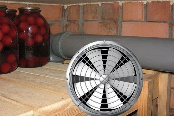
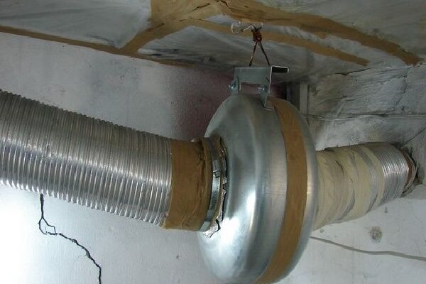
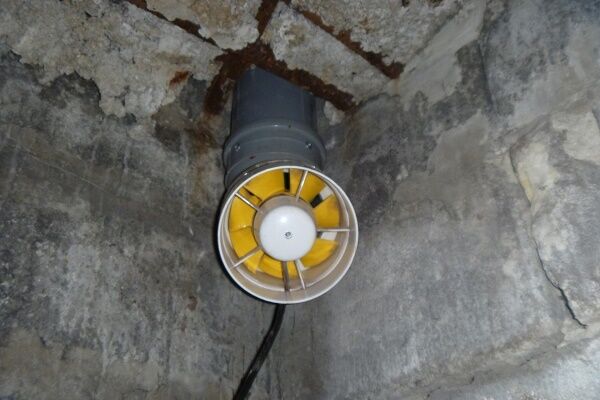
Selecting an Exhaust Fan
To decide on the choice of ventilation unit, you need to know the required performance of the ventilation complex and the resistance of the air ducts. For forced ventilation of the cellar, one fan built into the exhaust duct is sufficient.
The supply air duct, as a rule, does not require a ventilation unit. A small pressure difference between the points of air supply and air intake, provided by the operation of the exhaust fan, is sufficient.

You need a fan model whose performance is slightly (7-12%) higher than calculated.
You can check the suitability of the ventilation unit using a graph showing the dependence of performance on pressure loss.

If you have to choose between a clearly more powerful and a too weak ventilation unit, priority remains with the powerful model. However, you will need to somehow reduce its performance.
Optimization of an overpowered hood fan can be achieved in the following ways:
- Install a balancing throttle valve in front of the ventilation unit, allowing her to be “strangled.” If the exhaust duct is partially blocked, the air flow will decrease, but the fan will have to work with increased load.
- Turn on the ventilation unit to operate in low and medium speed modes. This is possible if the unit supports 5-8 speed adjustment or smooth acceleration. But low-cost fan models do not support multi-speed operating modes; they have a maximum of 3 speed adjustment stages. And for correct performance adjustment, three speeds are not enough.
- Reduce the maximum performance of the exhaust unit to a minimum. This is feasible if the fan automation allows control of its highest rotation speed.
Of course, you can ignore excessively high ventilation performance. However, you will have to overpay for electrical and thermal energy, since the hood will draw heat from the room too actively.
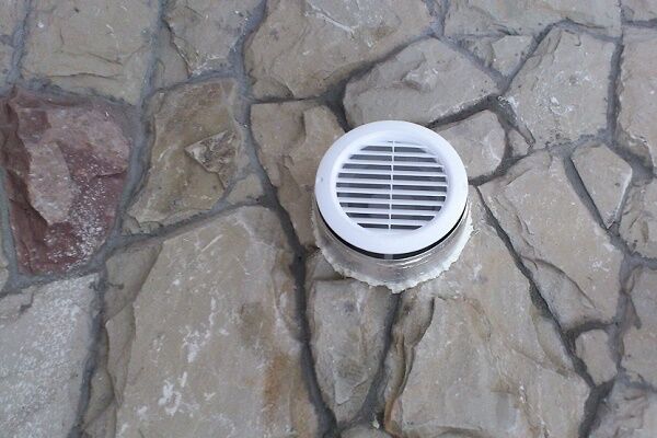
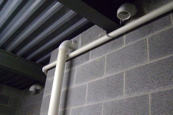
Basement ventilation duct diagram
The supply channel is led out beyond the facade of the basement and is arranged with a mesh fence around the opening. Its return outlet, through which air enters, descends to the floor at a distance of half a meter from the latter.
To minimize the formation of condensation, the supply channel must be thermally insulated from the outside, especially its “street” part.

The exhaust air intake is located near the ceiling, at the end of the room opposite from the point where the supply opening is located. Place the hood openings and supply channel on one side of the basement and on one level is pointless.
Since housing construction standards do not allow the use of vertical natural exhaust ducts for forced ventilation, air ducts cannot be installed on them.
There are cases when it is impossible to place the supply and exhaust air intake and discharge ducts on different sides of the cellar (there is only one façade wall). Then it is necessary to separate the air intake and discharge points vertically by 3 meters or more.
Conclusions and useful video on the topic
This video clearly demonstrates the signs of poor basement ventilation. There seem to be supply and exhaust air exchange channels in this cellar, but air does not flow through them. All the problems of the basement are evident - dampness, musty air and abundant condensation on the enclosing structures:
The video below shows a practical solution for forced exhaust of a cellar using a PC cooler and a solar panel. Let us note the originality of the execution of this ventilation project. For a “vegetable storage” type cellar, this implementation of air exchange is quite acceptable:
Since a complete decrease in humidity in the basement is impossible without thermal insulation of “cold” pipelines, we present a video about the application of tubular insulation. Note that for the technical purpose of the basement, it is rational to completely wrap the thermally insulated pipe with reinforced tape - this is more reliable:
It is quite possible to turn a “homeless” basement into a room for the desired purpose. It is only necessary to solve the problem of air exchange in it and eliminate sources of moisture. In any case, the basement level of the building should not be a wet, moldy place. After all, its walls are the foundation of a structure whose destruction is unacceptable.
Do you want to arrange your own ventilation in the cellarbut not sure if you're doing everything right? Ask your questions about the topic of the article in the block below. Here you can share your experience of independently arranging ventilation in a cellar or basement.


I've already suffered with my cellar. I bought a garage, and the cellar in it was not made like all normal people - under the garage, but in the other direction. That is, there is a street above it. Accordingly, every heavy rain on the street turns into a flood in the cellar. All this is aggravated by the lack of ventilation. There's only one pipe, and even that doesn't pull anything out. I would like to hear the opinion of knowledgeable people on the issue of installing forced ventilation: will it help get rid of dampness, is it necessary to pour the slab into the formwork above the cellar so that water does not get into it at all?
Ivan, do you have a warm cellar? If not, then simply wrap the pipe with insulation. I would still pour a slab as a ceiling over the cellar, and waterproof the entire ceiling. And why do you need forced ventilation? Do you spend a lot of time there? I have a gym in the basement, right there, my forced ventilation solved the problem with the musty smell and atmosphere.
Good afternoon, Ivan.
Forced ventilation will definitely reduce dampness significantly. Keep in mind in advance that after the flood she needs to work not for two or three hours, but for days.
With regard to the slab, everything is much more complicated. Waterproofing was not done properly. Most likely it is also arranged on the walls. The property of water is to look for a weak point, that is, it moves along the path of least resistance. After filling the slab, it will easily find another weak spot and the flooding will not stop, and the money will be spent.
Most likely the cellar is made of FBS. A major solution to the problem: dig around the perimeter and carry out waterproofing according to technology, only in this case the problem will be solved.
It is important to understand that after pouring the slab, excavation work will destroy its integrity. This will entail additional financial costs for restoration.
Good afternoon, Ivan.
Try penetrating waterproofing, which can be applied to the interior concrete or cement surfaces of underground structures. This is an alternative to opening up the soil around the cellar. The technology for processing protected surfaces is similar to painting - you can find it on the Internet.
Popular penetrating waterproofing agents are Penetron, Hydrotex, Xipex, Kalmatron, Vascon. I attached a screenshot with a description of Penetron. You will find the rest yourself.
I have a small basement, about 15 cubic meters and it has one ventilation pipe. making supply and exhaust ventilation is very problematic. Will a fan help in this case?
Hello! I suffered with condensation in the cellar. The cellar is located separately on the site. There is about 1m of land on top. The walls are treated with Penetron. The size of the cellar is 5X4X2.7.The supply pipe was located approximately 30cm from the floor, the outflow pipe approximately 20cm from the ceiling. The inflow and outflow are located diagonally relative to each other. Pipe diameter 110mm. Please tell me where I went wrong? And if I made a mistake, what needs to be corrected? Thanks in advance for the advice.
Yes, I forgot to add that the supply air is not felt at all (I checked it with a piece of paper and a lighter), the supply pipe is approximately 1 m above ground level. The outflow can be felt (the flame of the lighter is drawn in), the pipe is approximately 3m above ground level.