Supply and exhaust ventilation: operating principle and design features
In a room filled with fresh air, you can breathe easier, work more productively, and sleep better.But opening the window for ventilation every 2-3 hours is problematic, do you agree? Especially at night, when all family members are sleeping soundly.
One of the automated solutions for this task is supply and exhaust ventilation (PVV) of the room. But how to do it correctly? We will help you study the principle of operation and understand the features of the arrangement.
Our article discusses the components of the supply and exhaust system, the rules for their calculation and air exchange standards in rooms of various types.
Ventilation arrangement diagrams, photographs depicting individual elements of the system, and useful video recommendations for installing a ventilation system in a private home with your own hands are provided.
The content of the article:
What is ventilation?
How often do we ventilate the room? The answer should be as honest as possible: 1-2 times a day, if you remember to open the window. And how many times at night? A rhetorical question.
According to sanitary and hygienic standards, the total air mass in a room where people are constantly present must be completely renewed every 2 hours.
Conventional ventilation refers to the process of exchange of air masses between a confined space and the environment. This molecular kinetic process provides the ability to remove excess heat and moisture using a filtration system.
Ventilation also ensures that the air in the room meets sanitary and hygienic requirements, which imposes its own technological limitations on the equipment that will generate this process.
The ventilation subsystem is a set of technological devices and mechanisms for intake, exhaust, movement and purification of air. It is part of a comprehensive communications system for premises and buildings.
We recommend not to compare concepts ventilation and air conditioning – very similar categories that have a number of differences.
- Main idea. Air conditioning ensures the maintenance of certain air parameters in a confined space, namely temperature, humidity, degree of particle ionization, and the like. Ventilation produces a controlled replacement of the entire volume of air through inflow and outlet.
- Main feature. The air conditioning system works with the air that is in the room and the flow of fresh air itself may be completely absent. The ventilation system always operates at the boundary between the enclosed space and the environment through exchange.
- Means and methods. Unlike ventilation in a simplified form, air conditioning is a modular scheme of several blocks that processes a small part of the air and thus maintains sanitary and hygienic air parameters in the specified range.
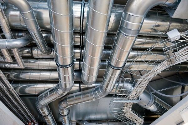
System ventilation in the house can be expanded to any required scale and provides, in the event of an emergency in the room, a fairly quick replacement of the entire volume of air mass. What happens with the help of powerful fans, heaters, filters and an extensive piping system.
You may be interested in the information on arranging a ventilation pipeline from plastic air ducts, discussed in our other article.

There are several classes of ventilation, which can be divided according to the method of generating pressure, distribution, architecture and purpose.
Artificial air injection in the system is carried out using injection units - fans, blowers. By increasing the pressure in the pipeline system, it is possible to move the gas-air mixture over long distances and in significant volumes.
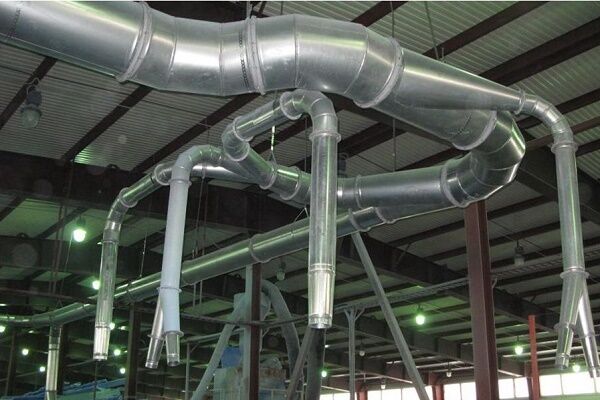
This is typical for industrial facilities, production premises and public facilities with a central ventilation system.

Local (local) and central ventilation systems are considered. Local ventilation systems are “spot”, narrowly targeted solutions for specific premises where strict compliance with standards is necessary.
Central ventilation provides the opportunity to create a regular exchange of air for a significant number of rooms with the same purpose.
And the last class of systems: supply, exhaust and combined. Supply and exhaust ventilation systems provide simultaneous supply and exhaust of air in a space. This is the most common subgroup of ventilation systems.
Such designs provide easy scaling and maintenance for a wide variety of industrial, office and residential premises.
Physical basis of the ventilation system
The supply and exhaust ventilation system is a multifunctional complex for ultra-fast processing of the gas-air mixture. Although this is a system of forced gas transportation, it is based on completely understandable physical processes.

The word “ventilation” itself is closely related to the concept of convection. It is one of the key elements in the movement of air masses.
Convection is the phenomenon of circulation of thermal energy between cold and warm gas flows. There is natural and forced convection.
A little school physics to understand the essence of what is happening. The temperature in the room is determined by the air temperature. Molecules are carriers of thermal energy.
Air is a multimolecular gas mixture that consists of nitrogen (78%), oxygen (21%) and other impurities (1%).
Being in a closed space (room), we have inhomogeneity of temperature relative to height. This is due to the heterogeneity of the concentration of molecules.
Considering the uniformity of gas pressure in a closed space (room), according to the basic equation of molecular kinetic theory: pressure is proportional to the product of the concentration of molecules and their average temperature.
If the pressure is the same everywhere, then the product of the concentration of molecules and the temperature at the top of the room will be equivalent to the same product of concentration and temperature:
p=nkT, ntop*Ttop=nbottom*Tbottom, ntop/nbottom=Tbottom/Ttop
The lower the temperature, the greater the concentration of molecules, and therefore the greater the total mass of the gas. This is why they say that warm air is “lighter” and cold air is “heavier”.

In connection with the above, the basic principle of arranging ventilation becomes clear: The air supply (inflow) is usually equipped from below the room, and the outlet (exhaust) is from above. This is an axiom that must be taken into account when designing a ventilation system.
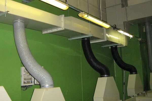
Features of supply and exhaust ventilation
Supply and exhaust ventilation interacts with two air flows of different composition and purpose, which are subsequently processed.
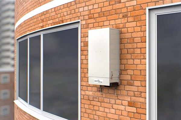
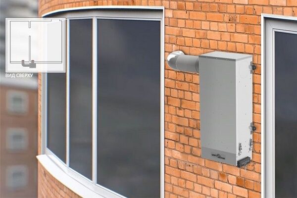
In the PVV, all the necessary equipment and additional systems are placed in a single frame, which can be installed inside the loggia, in the attic, on the wall outside the house, etc.
The special design of the installation provides ample opportunities to provide ventilation for almost any number of rooms in the building.
In addition to the main function of moving air, supply and exhaust ventilation includes the following arsenal of auxiliary subsystems and additional functions.
Among which are the following:
- air cooling and heating;
- ionization and humidification of particles;
- air disinfection and filtration.
Let's consider a typical operating cycle of a supply and exhaust ventilation system, which is based on a two-circuit transportation model.
At the first stage, cold air is taken in from the environment and warm air is extracted from the room. On both sides the air passes through a cleaning system.
The cold air is then transferred to heater (heater) - typical for PVV with heat recovery. In addition, heat is transferred to the cold gas from the warm exhaust air - typical for conventional systems.
After heating and heat exchange, the exhaust exhaust air is removed through an external duct, and the heated fresh air is supplied to the room.

The main principles of supply and exhaust ventilation are efficiency and economy.
The classic supply and exhaust ventilation scheme has the following advantages:
- high degree of purification of the input stream
- accessible operation and maintenance of removable elements
- integrity and modularity of the design.
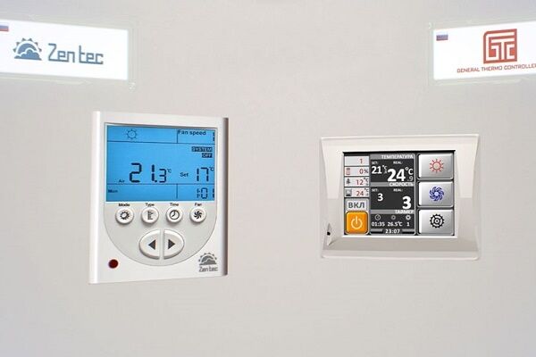
To expand the functionality, air handling units are equipped with auxiliary control and monitoring units, filter systems, sensors, auto timers, noise mufflers, electric motor overload alarms, recuperative units, condensate trays, etc.
Dynamic ventilation parameters
There are quite a lot of issues associated with the design of a ventilation system, since if the characteristics are incorrectly calculated, a completely economical ventilation system can be turned into a wasteful “monster” of energy resources.
Which directly affects the financial costs of its maintenance. As a result, the very idea of economical operation of equipment is not considered.

In order to correctly design supply and exhaust ventilation, it is recommended to make algebraic calculations of the installation’s performance and dynamic parameters of air flows.
There are several different calculation methods and algorithms, but we will present to our attention one of the simplest and most reliable options.
Everything related to the secondary processes of humidification, additional ionization and secondary purification can be ignored at this stage.
Construction standards
It is irrational to provide a complete list of sanitary norms and rules (SNiP) that apply to various ventilation systems, since there is enough material for a couple of books, but it is necessary to know the reference constants for residential and office premises.
As for office premises, when building a ventilation system, the main attention is paid to those areas where office personnel will be located.
Further, all standards are indicated per person. In a classic office building, on one floor there is a full range of premises with various purposes.
For example, in an office, 60 cubic meters of air should be replaced in one hour, in operating rooms - 30-40 m3, in the bathroom - 70 m3, in the smoking room - more than 100 m3, in corridors and lobbies - 10 m3.
According to general sanitary standards for residential premises, a complete exchange of air mass in the amount of 30 m occurs in one hour3 per person - calculation based on the number of residents.
There is another approach to calculating air volume - by area. For every square meter of living space there are 3 m3.

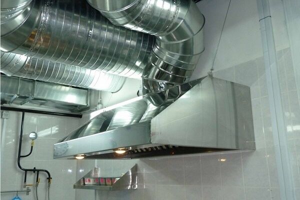
For the remaining utility rooms there are ready-made regulatory parameters. So, a kitchen with an electric stove - more than 60 m3, with a gas stove - more than 80 m3, bathroom - at least 25 m3 etc.
In addition, it must be remembered that for living rooms the air flow speed is no more than 2 m/s, and for the kitchen and bathroom the speed should be 4-6 m/s.
Formulas and explanations for them
Let's go directly to the characteristics and formulas. Calculations take place in several stages, at each of which we calculate one of the characteristics of the ventilation system.
Working air volume
Let's consider calculating the working volume of air (m3/h).
For an office, we recommend calculating the number of people:
V=35*N,
Where N - the number of people simultaneously in the room.
For apartments and private houses it is necessary to make a calculation regarding the volume of living space:
V=2*S*H,
Where: 2 — air exchange rate per unit time (per 1 hour); S - living space; H - height of the premises.
Calculation of duct cross-section
Section air duct for ventilation calculated in cm2. Main air ducts are of two types in cross-section: round and rectangular.
The cross-sectional area of the pipe is calculated according to the ratio:
Ssectioned=V*2.8/ω,
Where: Ssectioned - cross-sectional area; V — air volume (m3/h); 2,8 — dimensional matching coefficient; ω — flow speed in the main line (m/s).
The speed of air flow passing through the main line is usually equivalent to 2-3 m/s.

Number and size of diffusers
Let us next consider how to calculate the number and size of diffusers. The dimensions of the sprayer are usually chosen to be 1.5-2 times larger than the cross-sectional area of the main line.
The number of diffusers is a little more complicated; they are calculated using the formula:
N=V/(2820*ω*d2),
Where: N – the required number of diffusers; V – air mass flow (m3/h); ω – air flow speed (m/s); d – diffuser diameter (m), if it is round.
If the diffuser is rectangular, then:
N=π*V/(2820*ω*4*a*b),
Where: π - Pi, a And b - section dimensions.
Installation Performance Options
The two most important characteristics of the ventilation unit are known - power and the degree of pressure generated. The power of the ventilation station is calculated as follows:
P=ΔT*V*Cv/1000,
Where: ΔT — air temperature delta at the inlet/outlet (°C); V — air mass flow (m3/h); Cv — heat capacity of air (0.336 W*h/m³*°С).
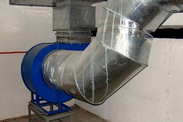
The generated pressure is determined from the performance characteristic curve of the main fan.
This parameter must be equivalent to the aerodynamic resistance of the air network. Fan manufacturers provide a curve graph in the product data sheet.
In addition, it is important to have a general understanding of the inlet air flow heater - air heater.This is a separate part of the ventilation system where the air is heated. Passing, for example, through a thermal radiator, the air thereby heats up.

In conclusion, it is worth mentioning the power supply voltage for the ventilation unit. It is recommended to use a 380 V mains voltage; it will ensure reliable operation of the installation of any power.
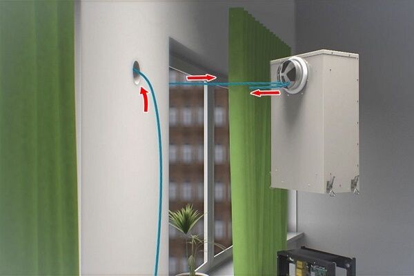
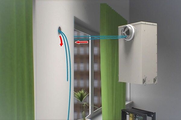
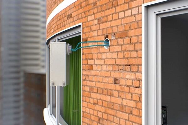
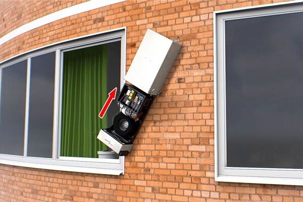
Specifics of installing mechanical ventilation
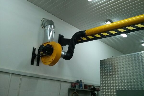
A home craftsman would undoubtedly be able to handle the installation of a supply-type ventilation unit without the involvement of workers.
However, it is worth remembering that the work is carried out at a dangerous height for an inexperienced performer. Therefore, it is better to involve those who have experience, tools and safety devices to perform the following steps:
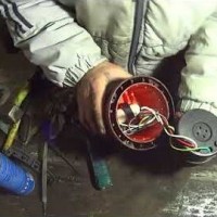
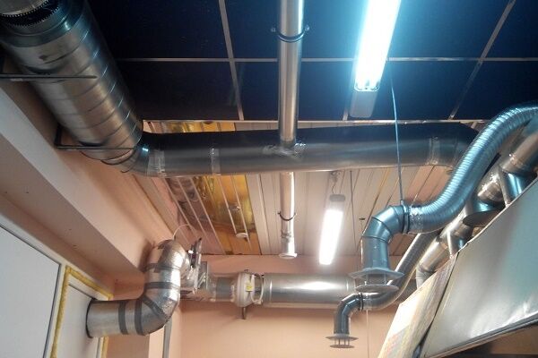
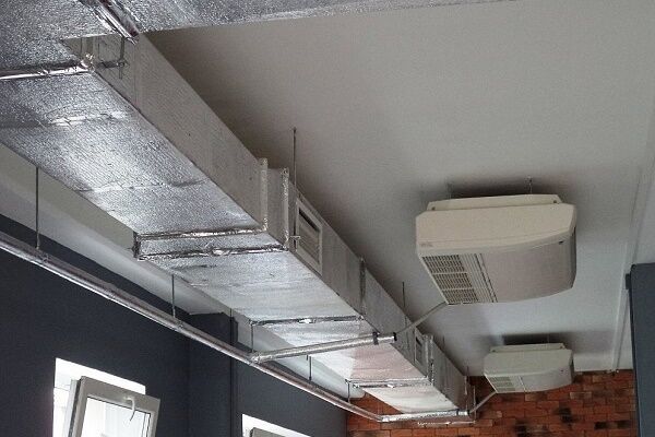
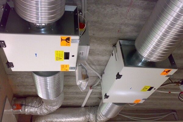
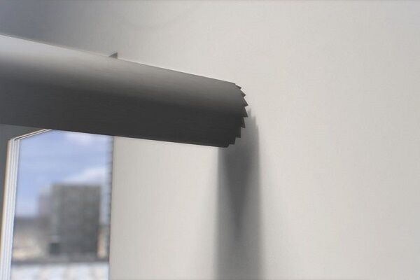
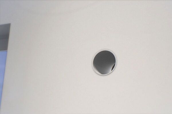
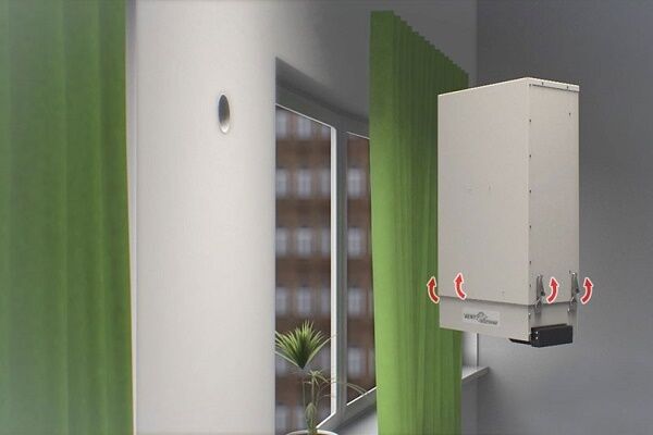
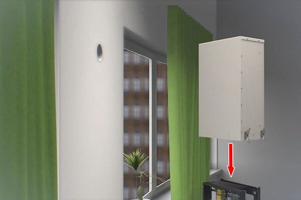
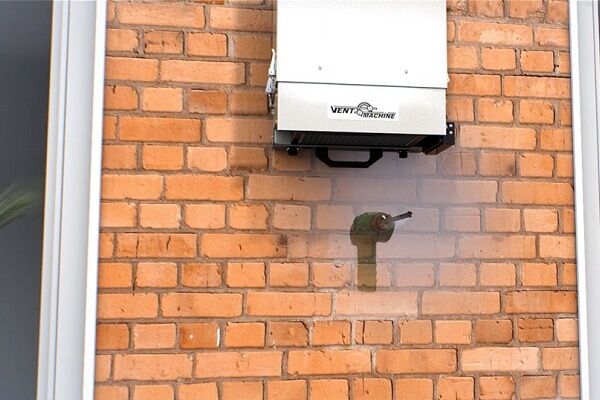
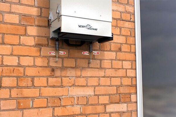
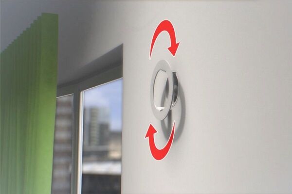
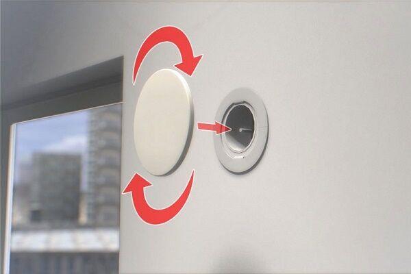
Upon completion of the very difficult manipulations of installing the air handling unit itself, all that remains is to connect it to the communications.
Let's take a closer look at this process using the following photo selection.
Information about the sequence of installation of forced ventilation units will help to avoid many of the most serious mistakes made by inexperienced installers.
Features of the construction of natural PVV
When developing high-quality natural supply and exhaust ventilation, most specialists comply with a certain “charter” of design and installation work.
These rules help create truly effective and cost-effective solutions even for the most non-standard arrangements of rooms and utility rooms. in a private house And multi-room apartment high-rise buildings.

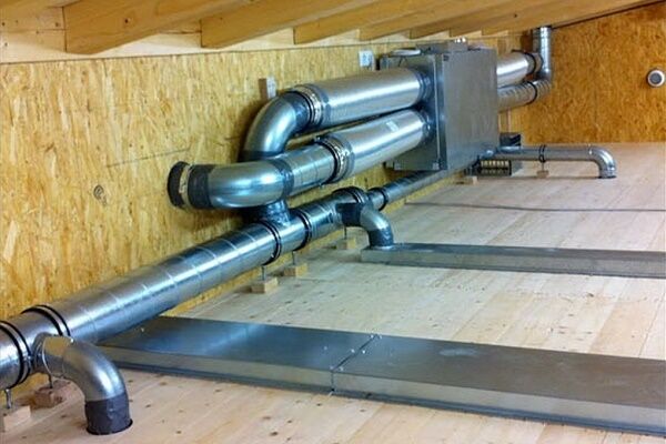
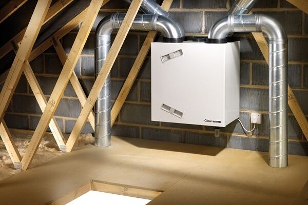
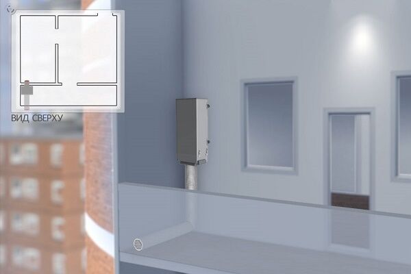
In this case, corridors act as flow spaces. Therefore, the main ventilation unit of the system should be located in the center of the house, at the top of the corridors or utility rooms.
For example, a ventilation module for a 2-story private house can be located on the ground floor at the top of a utility room or main corridor. For a 1-story house, as an option, in the lower part of the attic.
When laying the main pipeline, you need to remember that the supply air should go into the living rooms, and the exhaust air should go out through the kitchens and utility rooms.
Therefore, supply diffusers are placed at the conventional “room-environment” boundary, and hoods are placed in the kitchen, bathroom, utility room, and toilet.

There are comments regarding the height of the location of the inlet and outlet air openings. The outlet of the ventilation system must be located above the roof level of the building.
This will protect the PVV from the secondary intake of freshly exhausted air through the exhaust openings.
Fresh air must be taken in at a height of at least 2 meters from the ground surface.
Because small abrasive particles and dust can rise with the help of wind currents to a height of more than 1 meter and fly into the supply diffusers, thereby quickly clogging the primary filters.
Conclusions and useful video on the topic
The video explains and demonstrates the features of the design and installation of PVV in a private house:

Another clear example of a ready-made solution for ventilation of a private 1-story wooden house:

Summarizing the above information, we note that supply and exhaust ventilation is a simple system to design, available for purchase and installation.
Ventilation in conjunction with the heating system allows you to organize a balance of fresh and warm air in the room.
Have you been involved in arranging ventilation in your dacha? Or do you know the secrets of designing and installing a ventilation system in an apartment? Please share your experience - leave your comments on this article.


I really liked the way ventilation was used as an interior component. It’s good that you explained the principle of operation of the ventilation system, now at least I know how it all works. I didn’t realize that ventilation could cool or heat the air, this is very useful information. I especially liked these educational videos at the very bottom of the page.
The article describes the installation stage of the V-STAT FKO 4A installation, but now a new Satellite model has been released, much better and more compact. Looks like an external air conditioner unit.
Hello. As I understand it, your article contains a contradiction that I would like to resolve. First, it is stated that “To create the effect of natural convection of air flows, heat sources are placed as low as possible, and supply elements are placed in the CEILING or under it” (under the photo of a living room with a fireplace).
A few paragraphs later, the situation changes to the opposite: “In connection with the above, the basic principle of arranging ventilation becomes clear: the air supply (supply) is usually equipped at the BOTTOM of the room, and the outlet (exhaust) is at the top. This is an axiom that must be taken into account when designing a ventilation system.”
So where is it right to make an influx: at the top or at the bottom?
Hello. I’m not a super-professional in ventilation, but I’ll try to explain.
Inflow can be carried out in 4 main ways - top-down, top-up, bottom-up, bottom-down.
The first 2 methods are used when the air taken from the street in the winter and off-season is much lower than the temperature in the room, and the pressure and humidity of the air outside the window is higher.
The second and third are the most common in a natural ventilation device.
In the picture with the fireplace, the air inlet is most suitable for a room with such an appliance, which requires proper arrangement of the air supply system.
WATCH THE VIDEO “LIVING HOUSE”. IN IT, A VILLAGE RESIDENT EXPLAINS EVERYTHING ABOUT HOODING WITHOUT ELECTRICITY.