Standards for ventilation of a private house: requirements for the device and examples of calculations
The complex of works for the construction of a residential cottage necessarily includes the installation of a ventilation system. It performs a number of important functions.With the help of a constant flow of clean atmospheric air into the premises of the house and the removal of polluted air, your own home remains dry, and the air in it is fresh and healthy.
The system will work properly only if the ventilation standards for a private home are met and accurate calculations are made. They are produced during the development of the project in the “Ventilation” part. The calculated values will help you select the components of a system that provides standard air exchange.
We will talk about the specifics of organizing ventilation. We will tell you on the basis of what building codes and regulations, developed and approved by government bodies, design and calculations are carried out. Here you will find examples, using which you can calculate the system yourself.
The content of the article:
- Regulations for the low-rise sector SP 55.13330.2016
- General sanitary requirements in GOST 30494-2011
- Guide for designers SP 60. 13330.2016
- Air exchange in multi-storey buildings in SP 54.13330.2016
- Requirements for air exchange in MGSN 3.01-01
- Hygienic justifications in SanPiN 2.1.2.2645
- An example of calculating natural ventilation at home
- Conclusions and useful video on the topic
Regulations for the low-rise sector SP 55.13330.2016
This is one of the main sets of rules applied to the design of residential buildings with one apartment.The standards for ventilation of a private house collected in it relate to the design of autonomous residential buildings, the height of which is limited to three floors.
A comfortable microclimate is created in the interior of the building using ventilation equipment. Its characteristics are specified by GOST 30494-2011.
In most cases, an individual house is heated by an autonomous heating boiler. It is installed in rooms with good ventilation on the first or basement floors. Possibility of accommodation in the basement of the cottage. At power heat generator up to 35 kW it can be installed in the kitchen.

If the heating unit operates on gas or liquid fuel in the boiler room, measures are taken to thermally insulate equipment and pipelines in accordance with the conditions of SP 61.13330.2012.
The collection offers three principles for ventilation design:
- Exhaust air is removed from the premises by natural draft ventilation ducts. The influx of fresh air occurs due to ventilation of the rooms.
- Mechanical air supply and removal.
- Air intake naturally and the same removal by ventilation ducts and incomplete application of mechanical force.
In individual houses, air outflow is most often arranged from the kitchen and bathrooms. In other rooms it is organized as required and necessary.
The air flow from kitchens, bathrooms, restrooms with strong and not always pleasant odors is removed immediately outside. It must not enter other premises.
For natural ventilation, windows are equipped with vents, valves, and transoms.

The efficiency of ventilation equipment is calculated taking into account a single change of air within one hour in rooms with the constant presence of people.
Minimum volume of air removal in operating mode:
- from the kitchen – 60 m3/hour;
- from the bathroom – 25 m3/hour.
The air exchange rate for other rooms, as well as for all ventilated rooms with ventilation, but when it is turned off, is taken to be 0.2 of the total cubic capacity of the space.

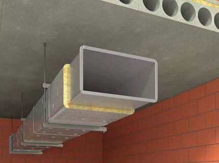
Cylindrical or rectangular air ducts are attached to building structures using various devices: hangers, brackets, lugs, brackets. All fastening methods must ensure the stability of ventilation lines and prevent deflection of ventilation pipes or ducts.
The temperature of the air duct surfaces is limited to 40O WITH.
Outdoor appliances are protected from low negative temperatures. To all structural parts ventilation systems free passage is provided for routine inspection or repair.
In addition, there are also collections of standards such as NP ABOK 5.2-2012. These are regulatory guidelines. air circulation in residential buildings. They were developed by non-profit partnership specialists ABOK in development of the regulations discussed above.
General sanitary requirements in GOST 30494-2011
A collection of state-approved standards for creating a comfortable living environment in residential buildings.
Indicators for air in residential apartments:
- temperature;
- moving speed;
- proportion of air humidity;
- total temperature.
Depending on the stated requirements, permissible or optimal values are used in calculations. You can see their full composition in Table No. 1 of the above standard. A condensed example version is given below.
For a living room the following are allowed:
- temperature – 18O-24O;
- humidity percentage – 60%;
- air movement speed – 0.2 m/sec.
For kitchen:
- temperature - 18-26 degrees;
- relative humidity – not standardized;
- the speed of movement of the air mixture is 0.2 m/sec.
For the bathroom, toilet:
- temperature - 18-26 degrees;
- relative humidity – not standardized;
- air movement rate is 0.2 m/sec.
During the warm season, microclimate indicators are not standardized.
The temperature environment inside the rooms is assessed using the usual tO air and the resulting The last value is a collective indicator tO air and radiation tO premises. It can be calculated using the formula in Appendix A by measuring the heating of all surfaces in the room. An easier way is to measure with a ball thermometer.

Air pollution inside a home is determined by the content of carbon dioxide, a product exhaled by people during breathing. Harmful emissions from furniture and linoleum are equal to an equivalent amount of CO2.
Indoor air and its quality are classified according to the content of this substance:
- Class 1 - high - carbon dioxide tolerance 400 cm and below3 at 1 m3;
- Class 2 – average – carbon dioxide tolerance 400 – 600 cm3 at 1 m3;
- Class 3 – permissible – СО approval2 — 1000 cm3/m3;
- Class 2 – low – carbon dioxide tolerance 1000 cm or higher3 at 1 m3.
The required volume of outside air for the ventilation system is determined by calculation using the formula:
L = k×Ls, Where
k — air distribution efficiency coefficient, given in Table 6 of GOST;
Ls – calculated, minimum amount of outside air.
For a system without forced traction k = 1.
He will familiarize you in detail with the calculations for providing premises with ventilation. next article, which is worth reading for both construction customers and owners of problematic housing.
Guide for designers SP 60. 13330.2016
This collection of rules is the main document for designers of a ventilation complex in a private house. This document establishes design rules ventilation system for all types of buildings. Here they also build on state standards for the microclimate of residential premises.
Sanitary and epidemiological indicators of residential buildings are used according to SanPin 2.1.2.2645.
The main postulates of the normative collection
The rules require that materials for air ducts and other parts of ventilation structures be purchased only if there are certificates confirming their compliance with sanitary and hygienic requirements.
To avoid condensation, air ducts must be thermally insulate according to SP 61.13330 standards. To protect against aggressive air components inside and outside the house, anti-corrosion materials are used or the surface of the boxes is coated with special compounds.
Installation and adjustment work is carried out in accordance with SP 73.13330.
Mechanically driven ventilation is used:
- if there is not enough natural air exchange;
- if the area is not equipped with air supply devices.
Mechanical ventilation is turned on when there is not enough natural circulation of the air mass during certain periods of time.
Ventilation system based on natural air circulation calculated based on the difference in densities of street air at a temperature of 5O C and density of internal air at standard temperature in the cold season of the year.
If at the above temperatures the air is not completely renewed, do supply and exhaust systems with mechanical impulse.
Receiving ventilation devices
They should not be located at a distance of less than 8 m from waste collection areas, parking lots with more than three cars, highways and other sources of harmful emissions and unpleasant odors.

In the upper zone of the building, the receiving structures are placed on the windward side. On hot days they are protected from direct sunlight and overheating.
The lower boundary of the ventilation intake compartment passes at a level of no more than 1 m from the snow surface, but not lower than 2 meters from the average ground level.
Air flow calculation
The calculation is made according to Appendix G of the current set of rules. From the calculation results, a greater value is taken that guarantees compliance with sanitary standards and safety in relation to fires and explosions.The amount of air entering the room should not be less than the minimum consumption calculated according to Appendices G and I.
Air costs are calculated separately for the summer and winter periods and the off-season using formulas G1-G7, choosing the highest value obtained:
- by excess heat;
- by weight of harmful and dangerous elements;
- by excess moisture;
- by multiplicity air circulation;
- according to consumption per 1 person.
The minimum consumption of external air cubic meters per hour per person is given in Table I1 of Appendix I.
Rules for organizing air exchange
Air is supplied to living spaces through special distributors in the upper part of the house. Receiving chambers for air outflow are made under the ceiling of the room at least 2 m from the floor to the bottom side of the hole to remove excess heat, excess moisture and gases.
Equipment and its placement
Fans are selected based on two indicators: resistance ventilation networks at a given speed of the air mixture in it and according to the calculated air consumption. In this case, the inflow and flow of air through leaky air is taken into account. fit parts in factory devices and air ducts as required by clause 7.11.8.

Transit distances of air ducts are designed in accordance with GOST REN 13779 for tightness class B, in other cases for class A.
Air suction and leakage through fire dampers and ventilation ducts accepted according to SP 5.13130.2009, to comply with the requirements of the Federal Law dated July 22, 2008. No. 123-FZ “TR on industrial safety requirements”.
Cleaning filters are selected taking into account the duration of operation, the amount of dust collected, and the degree of air purification.Outdoor air distributors must have devices for regulating the air flow vector and its flow rate.
In rooms with gas installations, fans are equipped with grilles and valves with air flow regulators. Their device guarantees incomplete closure.

Premises for the location of ventilation equipment, including technical floors and attics of residential buildings, are selected in accordance with the conditions of SP 54.13330 “Residential multi-apartment buildings”. Room category by explosively- and fire hazard is determined by Federal Law No. 123-FZ.
Shape and material of air ducts
In low-rise residential buildings, combining air ducts general exchange ventilation in a warm attic is ineffective. To prevent smoke, fire dampers and air barriers are installed on air ducts.
Ventilation ducts with limited fire resistance are made of non-combustible materials. Fire-resistant materials are also used for transit areas ventilation system and air ducts in rooms for placing equipment in basements and attics.
Materials with a flammability group higher than G1 are allowed:
- for air ducts of premises, except for the above;
- for flexible inserts of transit sections.
Ventilation ducts and pipes are made from unified standard parts. The use of asbestos cement in supply systems is not allowed. Air ducts must have coatings that are resistant to aggressive environments.

The thickness of sheet steel for the manufacture of air ducts is selected according to Appendix K of the regulatory collection under consideration.
At a permissible temperature of no higher than 80 degrees with a round diameter:
- up to 200 mm inclusive - sheet thickness 0.5 mm;
- from 250 to 450 mm - 0.6 mm;
- from 500 to 800 mm - 07 mm;
- from 900 to 1250 mm - 1.0 mm.
For rectangular ducts:
- up to 250 mm - 0.5 m;
- from 300 mm to 1000 mm - 0.7 mm;
- from 1250 to 2000 mm - 0.9 mm.
With an established fire resistance standard of at least 0.8 mm. It is not allowed to lay transit air ducts coming from premises for other purposes through kitchens and living rooms.
Gas pipelines, cables, wires, sewer pipes are allowed to be laid at a distance of more than 100 mm from the walls mounted air ducts. IN air exhaust It is not allowed to place domestic sewerage pipelines in mines.
The ducts and pipes of general exhaust ventilation are mounted with a rise of 0.005 in the direction of movement of the air mass. To remove the condensate that forms, drainage devices are provided.
Specifics of energy saving and automation
For private households, saving energy resources plays a significant role.
The total energy saving when designing ventilation systems is due to:
- selection of advanced equipment;
- solutions energy efficient tasks;
- application of mechanical systems;
- secondary use of heat from exhaust air;
- individual approach to regulating air exchange.
Electrical installations are selected taking into account standards PUE (7th edition) “Rules for electrical installations.” If there is a fire extinguishing and fire alarm system in the cottage, an automatic blocking of the power supply to the ventilation systems is designed in accordance with SP 7.13130.
In case of fire, it is planned to turn off the ventilation systems centrally or individually and turn on smoke protection. Remote control of smoke fire dampers, windows, transoms must be automated.
Air exchange in multi-storey buildings in SP 54.13330.2016
The postulates of this set of rules, intended for the construction of apartment buildings up to 75 meters high, will be useful when designing the ventilation of individual houses. Construction is carried out according to working drawings made on the basis of the project.
A residential building may have built-in, built-in and attached premises for general purposes and use: swimming pools, gyms, garages, parking lots, subject to the appropriate safety rules. The placement of industrial units in residential buildings is not permitted.
Rules for design MKD, developed based on sanitary requirements SanPiN 2.1.2.2645, GOST 30494 taking into account climatic zones according to SP 131.13330.
Noise protection is regulated by the conditions of SP 51.13330. The project of a residential building includes instructions for use, including the ventilation system.
An individual house is designed for one family. The composition of the premises and their number are provided at the customer’s request. Main premises: common living room, bedrooms, kitchen, bathrooms. Placing living rooms in basements is not permitted.

When designing saunas ventilation ducts equipped with fire dampers. Ventilation openings and pipeline entries in the foundation and basement structure of the building are provided with protective devices against rodents.
Air exchange rate:
- bedroom, living room with a total area of the mansion for 1 person. less than 20 sq.m. - 3 cubic meters / hour per 1 sq. meter of living space;
- more than 20 sq.m. – 30 cubic meters / hour for 1 person;
- kitchen with electric stove – 60 cubic meters/hour;
- room with gas equipment – 100 cubic meters/hour;
- a room with a heating boiler up to 50 kW with an open and closed firebox - hourly consumption equal to the volume of the room.
- bathroom, toilet – 25 cubic meters/hour.
In the outer walls of the basement, technical undergroundIn cold attics that do not have an exhaust hood, vents are made evenly distributed around the perimeter of the house. The area of one opening is at least 0.05 sq.m.
Requirements for air exchange in MGSN 3.01- 01
They specify all-Russian standards for the construction of residential buildings and partially repeat them.
The rate of air exchange increases according to the frequency of air exchange kitchen hoods with gas equipment depending on the number of gas burners:
- 2 pcs. – not less than 60 cubic meters/hour;
- 3 pieces – at least 75 cubic meters/hour;
- 4 pieces - at least 90 cubic meters/hour.
Gym in operating mode - 80 cubic meters/hour, non-operating - 16 cubic meters/hour;
An autonomous ventilation system is made for built-in objects. If there is a warm attic space, the exhaust shaft is provided with a height of at least 4.5 meters from the surface of the slabs covering the upper floor.
Hygienic justifications in SanPiN 2.1.2.2645
The collection dictates hygienic requirements for the ventilation system of the house, internal climate, and air condition. In accordance with its standards, it is not allowed for contaminated mixtures to escape from kitchens and bathrooms in general ventilation duct with living rooms.
Exhaust ventilation shafts rise above the roof ridge or flat roof to a height of at least 1 meter.

The permissible standards for temperature, relative humidity, and speed of air movement in the premises of the house during the cold and warm seasons of the year are listed.
An example of calculating natural ventilation at home
Current regulations offer three methods of calculation:
- by air exchange rate;
- according to sanitary and hygienic characteristics;
- by total area of rooms.
The calculations are based on two indicators: air flow in m3/hour and hourly air exchange rate. This data is taken from the sets of rules SP 54.13330 and SP 60.13330.
Multiplicity air circulation means the number of complete air updates in the room in 1 hour. Taken according to clause 9.1 of SNiP 01/31/2003.
According to standard settings, the following air flow rate is accepted:
- living room, bedroom - 1 time/hour;
- kitchen with electric stove - 60 cubic meters/hour;
- sanitary facilities – 25 m3/hour;
- room with a solid fuel boiler - multiplicity 1 + 100 m3/hour.
For kitchen in a house with a gas stove a scheme is adopted: a volume of air equal to the standard turnover is removed using natural exhaust, and the added 100 m3/hour are removed by forced ventilation in the form of a kitchen hood.

Exchange rate for boiler houses with gas heat generator is assumed to be equal to 3+ the volume of air for gas combustion.
Calculations by multiplicity and number of residents
Performed for each room of the cottage according to the formula:
L = S × h × n,
S – room area in m2;
h – room height m;
n – frequency of air exchange per hour, taken from SNiP.
The standard volume of air mass and the frequency of its change per day depends not only on the area of the space equipped by the system, but also on the number of residents. The following formula is used in hood calculations.
L = m × N, Where
L – air exhaust volume in m3/hour;
m – amount of air mixture per person m3/hour;
N - the number of people present in the room for at least 2 hours.
As an example, we consider a conventional house with the following premises:
- living room - 27 m2;
- bedroom 1 – 15 m2;
- bedroom 2 – 18 m2;
- kitchen - 16 m2;
- corridor – 10 m2;
- bathroom – 8 m2;
- bathroom – 4 m2.
Total - 98 m2.
Assuming that there are so many people living in a house that there is less than 20 m2 total area, then the hourly air flow is determined at the rate of 3 m3/hour per 1 m2 area. 98 × 3 = 294 m3/hour.
Air volumes are determined by cubic capacity of rooms with a height of 2.8 m:
- living room - 27 × 2.8 = 75.6 m3/hour;
- bedroom 1 - 15 × 2.8 = 42 m3/hour;
- bedroom 2 - 18 × 2.8 = 50.4 m3/hour;
- kitchen - 16 × 2.8 = 44.8 m3/hour;
- corridor - 10 × 2.8 = 28 m3/hour;
- bathroom - 8 × 2.8 = 22.4 m3/hour;
- bathroom – 4 × 2.8 = 11.2 m3/hour.
The obtained values, taking into account the air exchange rate, are rounded up to a multiple of five. The corridor used by the SNiP table is not standardized and is therefore excluded from the calculation.

The resulting volumes are summed up separately for air inflow and outflow.
Rooms with hood:
- kitchen - 44.8 not less than 90 m3/hour;
- bathroom - 22.4 not less than 25 m3/hour;
- bathroom - 11.2 not less than 25 m3/hour.
Total - 140 m3/hour.
Rooms from which fresh air comes:
- living room - 75.6 × 1 = 80 m3/hour;
- bedroom 1 – 42×1 = 45 m3/hour;
- bedroom 2 - 50.4×1 = 55 m3/hour;
Total - 180 m3/hour.
The inflow volume exceeds the outflow volume by 40 m3/hour. To balance the air flows, increase the volume of the hood by the missing amount, adding it to the volumes of the kitchen and bathroom.

After adjustment, accurate arrival and departure values are obtained.
Coming:
- living room - 75.6 × 1 = 80 m3/hour;
- bedroom 1 – 42×1 = 45 m3/hour;
- bedroom 2 - 50.4×1 = 55 m3/hour;
Total - 180 m3/hour
Care:
- kitchen - 44.8 not less than 105 m3/hour;
- bathroom – 22.4 not less than 25 m3/hour;
- bathroom – 11.2 not less than 50 m3/hour.
Total - 180 m3/hour.
The volumes are balanced according to the multiplicity calculation.
Accommodates 3 people + 2 guests intermittently. Norm – 60 m3/hour for 1 permanent resident, 20 m3/hour for 1 temporary resident.
Calculations:
- living room - 3 × 60 + 2 × 20 = 220 m3/hour;
- bedroom 1 - 2 × 60 = 120 m3/hour;
- bedroom 2 – 1 × 60 = 60 m3/hour.
Total - 400 m3/hour.
The hood, calculated above according to the multiplicity standards, is increased to the total volume of the air supply, spreading the difference 400 - 180 = 220 m3/ an hour to extract from the kitchen, bathroom and toilet.
Receive:
- kitchen – 105 m3/hour = 280 m3/hour
- bathroom – 25 m3/hour = 60 m3/hour;
- bathroom - 50 m3/hour = 60 m3/hour.
Total - 400 m3/hour. The calculated value of the hood diameter should ensure a complete change of air mass in a private house.
Calculation according to sanitary standards
The area of the house is 98 sq.m. Supply air exchange taking into account the norm of 3 m3 at 1 m2 area. 98 × 3 = 294 m3/hour.
This result is distributed across all rooms with a hood:
- kitchen – 90 m3/hour = 174 m3/hour;
- bathroom – 25 m3/hour = 60 m3/hour;
- bathroom – 25 m3/hour = 60 m3/hour.
Total - 294 m3/hour.
Achieving equilibrium in air exchange is the basis of ventilation calculations.
Calculation of the cross-section of air ducts
Now the task is to distribute the flows. The hood will consist of four channels: two in the kitchen and one each in the bathroom and toilet.
It can be calculated using two formulas:
A) F = L/3600×V , Where
F – cross-sectional area of the air duct m2;
L — consumption of exhaust mixture m3/hour;
V – air flow speed m/sec.
b) F = 2.778 × L/V , Where
2.778 is the conversion factor from values in meters to centimeters.
In channels with natural exhaust rate of movement of air mass limited to the range from 0.5 to 1.5 m/sec. Accepted for the selected house is 0.8 m/sec.
100 cubic meters air in the kitchen will go through a duct with an exhaust fan while cooking on the stove. For natural air exchange, 180 cubic meters remain in the kitchen. Calculate the circular cross-section of the air duct for a kitchen duct with natural draft.
F = 2.778 × 180/0.8 = 625 cm2.
Area of a circle = n×R2, where n = 3.14.
625 = 3.14×R2, R = 14.1 cm, the calculated diameter of the hood in a private house is 282 mm.
Similarly, the channels for the bathroom and toilet will have a cross-section of 163 mm each.
F = 2.778 × 60/0.8 = 208 cm2.
Area of a circle = n×R2.
208 = 3.14×R2, R = 8.13 cm, section value determined ventilation duct in a private house with a diameter of 163 mm.
You can select air ducts using special diagrams with two coordinate axes: air mixture flow rate and air transportation speed. At the intersection of perpendiculars from these values for a specific air duct, the values of its diameter are found.

The selection of the standard size of ventilation ducts is carried out according to GOST, taking into account the calculations performed. For example, GOST 14918-80 is used for air ducts made of galvanized steel, and GOST 17079-88 for reinforced concrete.
To calculate ventilation systems and implement them in drawings and three-dimensional images, designers use reference books and computer programs developed on the basis of building codes: ventilation calculation algorithm Vent—Calc, selection of air ducts – Ducter 2.5, drawing ventilation SVENT, CADvent.
Conclusions and useful video on the topic
The following video will introduce you to the rules for designing installations and systems for standard air exchange:
Ventilation standards are developed not only to make the work of designers easier. Knowing them is useful for construction customers and homeowners who are not provided with an adequate supply of fresh air. If the owners independently identify violations in the project, they will be able to get the errors corrected or at least receive compensation.
Would you like to talk about how the ventilation system works in your own home/apartment/dacha? Please leave comments in the block form below. In it you can share useful information on the topic, ask a question and post a photo.


