Heating system distribution comb: purpose, principle of operation, connection rules
Owners of country cottages and private houses are increasingly abandoning traditional one- or two-pipe wiring and prefer a manifold distributor.This allows you to use fuel more economically and create comfortable conditions in each room separately. Agree that it is irrational to refuse to reduce heating costs, especially since the temperature in the premises will not suffer from this.
Are you also thinking about connecting a collector and want to learn more about this equipment? We will help you understand the topic - in this article we will look in detail at what the distribution comb of a heating system is and what its advantages are.
We will highlight the significant disadvantages of its use, describe the connection process in detail, providing the material with visual photos. We will also focus on the basic connection rules that it is advisable to follow. Here are useful video recommendations for installing and making your own comb.
The content of the article:
Purpose of the distribution comb
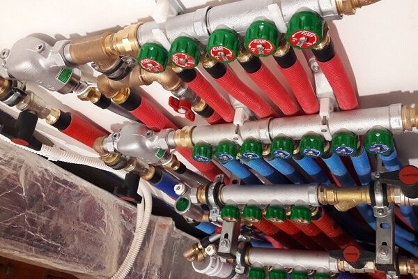
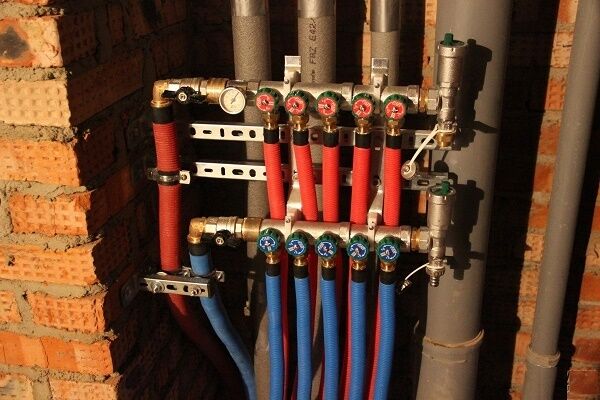
Heating manifolds (distribution combs) are an important component of a modern heating system. In a simplified form, the comb can be represented as a pipe with a plug at the end and several outlets in the form of pipes, allowing the coolant to be directed to individual points.
The number of outlets varies - it depends on the specific heating system and the number of heating devices planned for connection.
With the help of a collector, coolant flows in the heating circuit are optimized.It also smoothes out pressure surges (water hammer), appearing due to the operation of boiler automation that regulates temperature conditions.
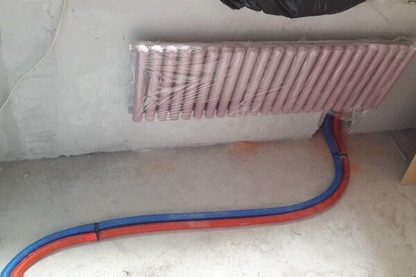
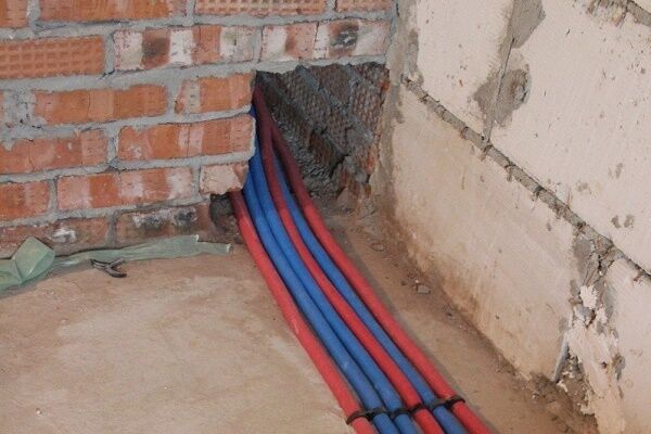
Heating combs are needed for arranging heated floors, but they are also used in radiator heating systems. Radiators are connected to the collector via beam scheme, i.e. each of them has its own supply pipe and return pipe, through which the coolant returns to the collector.
This heat distribution ensures uniform heating of the radiators and makes it possible to regulate the temperature in a particular room or completely disconnect it from the heating system.

Another purpose of the comb is to connect additional devices - for example, in a house where there is already heating, a swimming pool has been built, and now it is necessary to heat the water in it.
You can also connect secondary energy sources to it - for example, solar panels.

Let's list the benefits of purchasing a comb:
- uniform distribution of coolant, facilitating temperature control;
- local setting of set temperatures, heating only the necessary rooms;
- protection of the heating network from water hammer.
Commercially available distribution combs today are cost-effective and high-tech equipment with a lot of sensors that monitor temperature, react to deviations, signal problems, etc.
Design of different types of combs
The most affordable would be a distribution comb with manual shut-off valves made in China or Turkey. On the collet connectors located on it, put on metal-plastic pipes.

Threads at the ends are needed for connecting shut-off valves and central hot water supply/discharge. In general, such a comb will cope with its function, but its flawless service life will not be very long.
If disassembling the valves and replacing worn seals does not lead to initial tightness, you will have to buy a new manifold.
A more complex design would be a comb with plugs on the return manifold (and on the direct one too). Instead of them, flow meters and thermal heads can be installed in the future. The direct and reverse combs in such models are already connected by a bracket for mounting on the wall.

And finally, a complex and expensive, but the most effective distribution comb with factory-installed flow meters and thermal heads.
Flow meters regulate the uniform delivery of coolant to its destination, and thermal heads can adjust the temperature for each outlet separately, just like for a heating radiator. More details types of thermal heads, the principle of their operation and installation features are discussed in our other article.

Even during the design process, it is necessary to make a choice between different types of combs, but in any case, the collector system is a preferable choice compared to conventional wiring based on such criteria as ease of use and durability.
Operating principle of the distribution manifold
In modern heating systems, two types of distribution manifolds are used - for boiler rooms and local. They have different dimensions and a slightly different operating principle.
In the boiler manifold, the supply comb supplies the coolant to the parts of the heating system, so it is equipped not only with taps, but also with circulation pumps. The second comb is the receiving one.
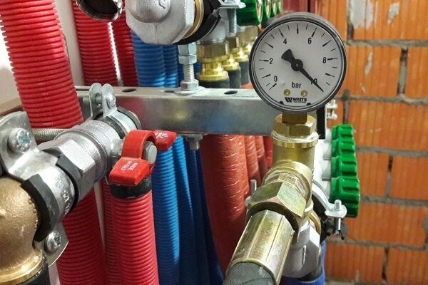
In addition, pressure and temperature sensors and a very important element are installed on the manifold - hydraulic arrow. It maintains an optimal temperature difference between supply and return.

The local distribution comb differs from the central manifold installed in the boiler room, both in size and operating principle. There may be several of them in a heating system.
If in the main collector the cooled water is completely replaced by hot water from the boiler, then in the small combs the circulating water is diluted.
The coolant in them moves in a closed circle until its temperature drops below a predetermined level.
Compliance with the temperature regime is monitored by a sensor, which, when the temperature drops critically, opens a valve that blocks the path of water from the boiler main. Hotter water enters, mixing with the cooled water.

There is no hydraulic arrow in such collectors; it is replaced by an additional circulation pump. It pushes the coolant in a circular space, periodically throwing in a portion of hot water from the supply line. In this case, the same amount of cooled water is returned there, but into another pipe - the return pipe.
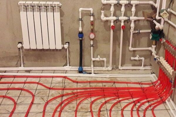
Local combs are used both in heated floors and for connecting radiators.

To achieve highly efficient functioning of the heating system throughout the house as a whole, it is recommended to build into it both a central distribution manifold and the required number of local combs. Together they will give the desired result.
Calculation of comb throughput
The calculation of the parameters of the distribution comb includes determining its length, the cross-sectional area of its cross-section and pipes, and the number of heat supply circuits.It is better if the calculations are done by engineers using computer programs; in a simplified version, they are only suitable at the preliminary design stage.
In order to maintain hydraulic balance, the diameters of the inlet and outlet manifold combs must match, and the total throughput capacity of the nozzles must be equal to the same parameter of the collector pipe (the rule of total sections):
n=n1+n2+n3+n4,
Where:
- n is the cross-sectional area of the collector4
- n1,n2,n3,n4 - cross-sectional areas of the pipes.
The choice of comb must correspond to the maximum thermal output of the heating system. What power the factory product is designed for is written in the technical data sheet.
For example, a distribution pipe diameter of 90 mm is used for a power not exceeding 50 kW, and if the power is twice as high, the diameter will have to be increased to 110 mm. This is the only way to eliminate the risk of unbalancing the heating system.

The 3-diameter rule is also useful (see picture above). As for calculating the performance of the circulation pump, the specific water consumption in the heating system is taken as the basis.
Each pump is calculated separately - per circuit and for the entire system. The figures obtained in the calculation are rounded up. A little extra power is better than too little.
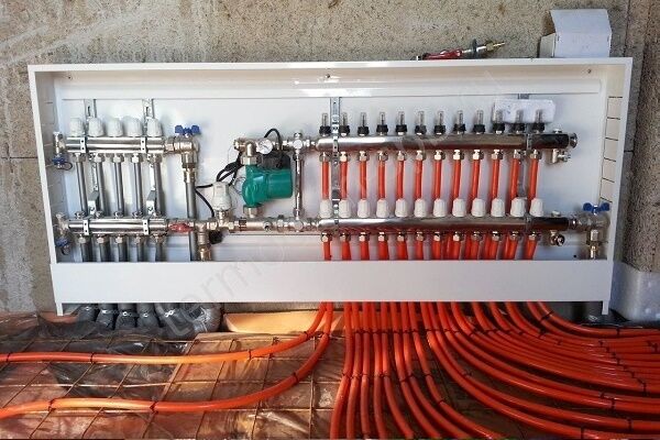
Connection rules and installation features
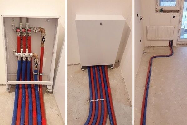
Installation of the comb begins with attaching it with brackets to the wall, where it will be located openly or in a closet.Then you will need to attach the main pipes from the heat source to the ends and begin piping.
Option #1 - without additional pumps and hydraulic arrows
This simple option assumes that the comb will serve several circuits (say, 4-5 radiator batteries), the temperature is assumed to be the same, and its regulation is not provided. All circuits are connected directly to the comb, one pump is used.
The characteristics of pumping equipment must be correlated with the performance of the heating system and the pressure created in it. So that you can choose the best pump that is ideal in terms of characteristics and cost, we recommend that you familiarize yourself with rating of circulation pumps.

Since the resistance in the circuits is different (due to different lengths, etc.), it is necessary to ensure optimal consumption of the coolant by balancing.
To do this, balancing valves, rather than shut-off valves, are installed on the return comb nozzles. They can regulate (although not exactly, but by eye) the coolant flow in each circuit.
Option #2 - with pumps on each branch and hydraulic arrow
This is a more complex option, which will be needed if necessary to power consumption points with different temperature conditions.
So, for example, in radiator heating, water heating ranges from 40 to 70 °C, a warm floor needs a range of 30-45 °C, hot water for domestic needs must be heated to 85 °C.
In the piping, the hydraulic arrow will now play a special role - a section of pipe that is blind at both ends and has two pairs of bends.The first pair is needed to connect the hydraulic needle to the boiler; the distribution combs are connected to the second pair. This is a hydraulic barrier that creates a zone of zero resistance.

On the comb itself there are mixing units equipped three way valves - temperature control devices. Each outlet pipe operates its own pump independently of the others, providing the specific circuit with the required amount of coolant.
The main thing is that the total power of these pumps does not exceed the main boiler pump.
Both options considered are used when installing distribution manifolds for boiler houses. Everything you need is sold in specialized stores. There you can buy any assembly assembled or element by element (counting on savings due to self-assembly).
To further reduce future costs, the heating distribution comb Can make it yourself.
The boiler room manifold is located in close proximity to the heating equipment and is exposed to high temperatures that only metal can withstand.
The local distribution comb is subject to less stringent requirements for heat resistance; not only metal pipes, but also polypropylene and metal-plastic pipes are suitable for its manufacture.
For a local distribution manifold, the easiest way is to select suitable scallops from those that are commercially available. In this case, you should take into account the material from which they are made - brass, steel, cast iron, plastic.
Cast scallops are more reliable, eliminating the possibility of leakage. There are no problems connecting pipes to the manifolds - even the most inexpensive models have threads.

Craftsmen can solder a manifold from polypropylene or metal-plastic, but they will still have to buy threaded tips, so the product will not be much cheaper in terms of money than a ready-made one from the store.
Externally, it will be a set of tees connected to each other by tubes. The weak point of such a collector is insufficient strength at high heating temperatures of the coolant.
The comb can be round, rectangular, or square in cross-section. Here, the transverse area comes first, rather than the cross-sectional shape, although from the standpoint of hydraulic laws, rounded is preferable. If the house has several floors, it is better to install local distribution manifolds on each of them.
What you need to know about the cons?
After the advantages of using distribution combs in heating systems have become clear, it makes sense to dwell on some of the disadvantages:
- High price. Collectors are made of durable, high-quality metal, the cost of which is above average. High-precision locking equipment is also expensive. The more circuits a comb serves, the higher the cost of equipping it.
- Energy dependence. Collector heating without a circulation pump does not work. Therefore, you need to prepare for additional payments for electricity.
- High pipe flow. Pipe flow in collector heating systems several times higher than in conventional ones, since a separate loop needs to be pulled to each device.All this complicates and increases the cost of installation work.
The collector system, according to experts and those who already use it, is the most modern, reliable and efficient.
But at the same time, both its arrangement and operation are expensive.
Conclusions and useful video on the topic
Installation of heating equipment with connection to the distribution comb:
Making a comb with your own hands:
Compared to the traditional organization of a heating system, distribution combs increase its efficiency, and only the financial issue somewhat inhibits consumer interest in this heating method. But if you have enough money, using distributor combs is your ideal choice.
Have you implemented a collector heating system in your home? Or are you just planning its arrangement and something is not clear to you? Ask questions - we will try to answer them.
Or maybe you used a comb to connect a heated floor system? Share your personal experience of assembling and installing the system - leave your comments in the block below.


A fairly detailed description of all the processes required to install such a heating system. I, as a person who understands this, having worked for many years in a company installing heating devices, can say that even a beginner with such instructions will be able to install everything. Moreover, I even discovered several secrets for myself. Thanks a lot)