Supply and exhaust ventilation with heat recovery: principle of operation, review of advantages and disadvantages
The supply of fresh air during the cold period leads to the need to heat it to ensure the correct indoor microclimate.To minimize energy costs, supply and exhaust ventilation with heat recovery can be used.
Understanding the principles of its operation will allow you to most effectively reduce heat loss while maintaining a sufficient volume of replaced air. Let's try to understand this issue.
The content of the article:
Energy saving in ventilation systems
In the autumn-spring period, when ventilating rooms, a serious problem is the large temperature difference between the incoming air and the air inside. The cold flow rushes down and creates an unfavorable microclimate in residential buildings, offices and factories or an unacceptable vertical temperature gradient in a warehouse.
A common solution to the problem is integration into supply ventilation air heater, with the help of which the flow is heated. Such a system requires energy consumption, while a significant volume of warm air escaping outside leads to significant heat loss.
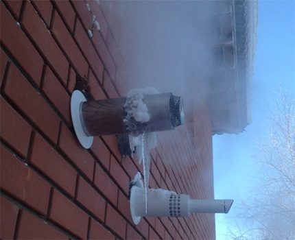
If the air inlet and outlet channels are located nearby, then it is possible to partially transfer the heat of the outgoing flow to the incoming one.This will reduce the energy consumption of the heater or eliminate it altogether. A device for ensuring heat exchange between gas flows of different temperatures is called a recuperator.
During the warm season, when the outside air temperature is significantly higher than room temperature, a recuperator can be used to cool the incoming flow.
Design of a unit with a recuperator
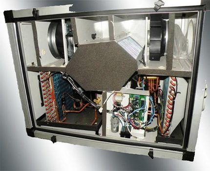
Internal structure of supply and exhaust ventilation systems with integrated recuperator They are quite simple, so they can be purchased and installed independently element by element. If assembly or self-installation is difficult, you can purchase ready-made solutions in the form of standard monoblock or individual prefabricated structures to order.
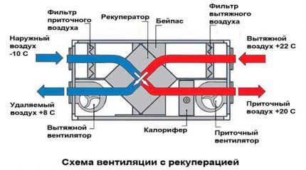
Main elements and their parameters
The body with heat and noise insulation is usually made of sheet steel. In the case of wall installation, it must withstand the pressure that occurs when foaming the cracks around the unit, and also prevent vibration from the operation of fans.
In the case of distributed air intake and flow in various rooms, connect to the housing air duct system. It is equipped with valves and dampers to distribute flows.
If there are no air ducts, a grille or diffuser is installed on the supply opening on the side of the room to distribute the air flow. An external type air intake grille is installed on the inlet opening on the street side to prevent birds, large insects and debris from entering the ventilation system.
Air movement is provided by two fans of axial or centrifugal action. In the presence of a recuperator, natural air circulation in a sufficient volume is impossible due to the aerodynamic resistance created by this unit.
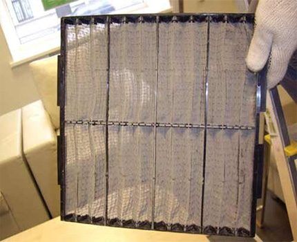
The presence of a recuperator involves the installation of fine filters at the inlet of both flows. This is necessary to reduce the intensity of clogging of thin heat exchanger channels with dust and grease deposits. Otherwise, for the system to function fully, it will be necessary to increase the frequency of preventive maintenance.
One or more recuperators occupy the main volume of the supply and exhaust device. They are mounted in the center of the structure.
In the case of severe frosts typical for the territory and insufficient efficiency of the recuperator to heat the outside air, you can additionally install a heater. Also, if necessary, a humidifier, ionizer and other devices are installed to create a favorable microclimate in the room.
Modern models include an electronic control unit. Complex modifications have functions for programming operating modes depending on the physical parameters of the air environment. External panels have an attractive appearance, thanks to which they can fit well into any interior.
Solving the problem of condensation
Cooling the air coming from the room creates the prerequisites for the release of moisture and the formation of condensation. In the case of a high flow rate, most of it does not have time to accumulate in the recuperator and goes outside.With slow air movement, a significant part of the water remains inside the device. Therefore, it is necessary to ensure that moisture is collected and removed outside the housing. supply and exhaust system.

Moisture is removed into a closed container. It is placed only indoors to avoid freezing of the outflow channels at sub-zero temperatures. There is no algorithm for reliable calculation of the volume of water received when using systems with a recuperator, so it is determined experimentally.
Reusing condensate for air humidification is undesirable, since water absorbs many pollutants such as human sweat, odors, etc.
You can significantly reduce the volume of condensate and avoid problems associated with its occurrence by organizing a separate exhaust system from the bathroom and kitchen. It is in these rooms that the air has the highest humidity. If there are several exhaust systems, the air exchange between the technical and residential areas must be limited by installing check valves.
If the exhaust air flow is cooled to negative temperatures inside the recuperator, condensate turns into ice, which causes a reduction in the open cross-section of the flow and, as a consequence, a decrease in volume or a complete cessation of ventilation.
For periodic or one-time defrosting of the recuperator, a bypass is installed - a bypass channel for the movement of supply air. When a flow bypasses the device, heat transfer stops, the heat exchanger heats up and the ice passes into a liquid state. The water flows into the condensate collection tank or evaporates outside.

When the flow passes through the bypass, there is no heating of the supply air through the recuperator. Therefore, when this mode is activated, the heater must automatically turn on.
Features of various types of recuperators
There are several structurally different options for implementing heat exchange between cold and heated air flows. Each of them has its own distinctive features, which determine the main purpose for each type of recuperator.
Plate cross-flow recuperator
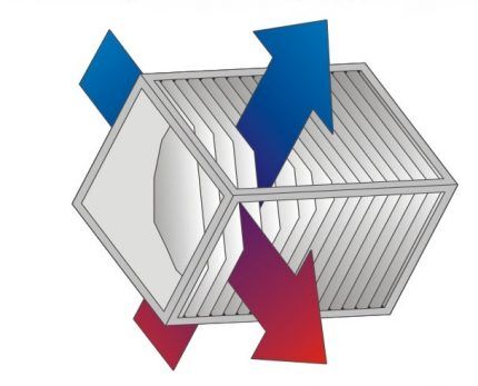
The design of the plate recuperator is based on thin-walled panels, connected alternately in such a way as to alternate the passage of flows of different temperatures between them at an angle of 90 degrees. One of the modifications of this model is a device with finned channels for air passage. It has a higher heat transfer coefficient.
Heat exchange panels can be made of various materials:
- copper, brass and aluminum-based alloys have good thermal conductivity and are not susceptible to rust;
- plastic made from a hydrophobic polymer material with a high thermal conductivity coefficient and low weight;
- hygroscopic cellulose allows condensation to penetrate through the plate and back into the room.
The disadvantage is the possibility of condensation forming at low temperatures.Due to the small distance between the plates, moisture or ice significantly increases aerodynamic drag. In case of freezing, it is necessary to block the incoming air flow to warm the plates.
The advantages of plate recuperators are as follows:
- low cost;
- long service life;
- long period between preventive maintenance and ease of its implementation;
- small dimensions and weight.
This type of recuperator is most common for residential and office premises. It is also used in some technological processes, for example, to optimize fuel combustion during the operation of furnaces.
Drum or rotary type
The operating principle of a rotary recuperator is based on the rotation of a heat exchanger, inside of which there are layers of corrugated metal with high heat capacity. As a result of interaction with the outgoing flow, the drum sector is heated, which subsequently gives off heat to the incoming air.
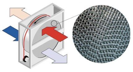
The advantages of rotary recuperators are as follows:
- quite high efficiency compared to competing types;
- return of a large amount of moisture, which remains in the form of condensation on the drum and evaporates upon contact with incoming dry air.
This type of recuperator is less often used for residential buildings for apartment or cottage ventilation. It is often used in large boiler houses to return heat to furnaces or for large industrial or commercial premises.
However, this type of device has significant disadvantages:
- a relatively complex design with moving parts, including an electric motor, drum and belt drive, which requires constant maintenance;
- increased noise level.
Sometimes for devices of this type you can come across the term “regenerative heat exchanger”, which is more correct than “recuperator”. The fact is that a small part of the exhaust air gets back due to the loose fit of the drum to the body of the structure.
This imposes additional restrictions on the ability to use devices of this type. For example, polluted air from heating stoves cannot be used as a coolant.
Tube and casing system
A tubular type recuperator consists of a system of thin-walled tubes of small diameter located in an insulated casing, through which there is an influx of outside air. The casing removes warm air from the room, which heats the incoming flow.

The main advantages of tubular recuperators are as follows:
- high efficiency due to the countercurrent principle of movement of the coolant and incoming air;
- simplicity of design and absence of moving parts ensures low noise levels and rarely requires maintenance;
- long service life;
- the smallest cross-section among all types of recovery devices.
Tubes for this type of device use either light-alloy metal or, less commonly, polymer. These materials are not hygroscopic, therefore, with a significant difference in flow temperatures, intense condensation may form in the casing, which requires a constructive solution for its removal.Another disadvantage is that the metal filling has significant weight, despite its small dimensions.
The simplicity of the design of a tubular recuperator makes this type of device popular for self-production. Plastic pipes for air ducts, insulated with a polyurethane foam shell, are usually used as an external casing.
Device with intermediate coolant
Sometimes the supply and exhaust air ducts are located at some distance from each other. This situation may arise due to the technological features of the building or sanitary requirements for reliable separation of air flows.
In this case, an intermediate coolant is used, circulating between the air ducts through an insulated pipeline. Water or a water-glycol solution is used as a medium for transferring thermal energy, the circulation of which is ensured by operation heat pump.
If it is possible to use another type of recuperator, then it is better not to use a system with an intermediate coolant, since it has the following significant disadvantages:
- low efficiency compared to other types of devices, therefore such devices are not used for small rooms with low air flow;
- significant volume and weight of the entire system;
- the need for an additional electric pump to circulate the liquid;
- increased noise from the pump.
There is a modification of this system when, instead of forced circulation of the heat exchange fluid, a medium with a low boiling point, such as freon, is used.In this case, movement along the contour is possible naturally, but only if the supply air duct is located above the exhaust air duct.
Such a system does not require additional energy costs, but only works for heating when there is a significant temperature difference. In addition, it is necessary to fine-tune the point at which the state of aggregation of the heat exchange fluid changes, which can be achieved by creating the required pressure or a certain chemical composition.
Main technical parameters
Knowing the required performance of the ventilation system and the heat exchange efficiency of the recuperator, it is easy to calculate savings on air heating for a room under specific climatic conditions. By comparing the potential benefits with the costs of purchasing and maintaining the system, you can reasonably make a choice in favor of a recuperator or a standard air heater.

Efficiency
The efficiency of a recuperator is understood as the efficiency of heat transfer, which is calculated using the following formula:
K = (TP - Tn) / (TV - Tn)
Wherein:
- TP – temperature of the air entering the room;
- Tn – outside air temperature;
- TV – room air temperature.
Maximum efficiency value at standard air flow speed and a certain temperature regime are indicated in the technical documentation of the device. Its actual figure will be slightly less.
In the case of self-manufacturing of a plate or tubular recuperator, in order to achieve maximum heat transfer efficiency, you must adhere to the following rules:
- The best heat transfer is provided by counter-flow devices, then cross-flow devices, and the least by unidirectional movement of both flows.
- The intensity of heat transfer depends on the material and thickness of the walls separating the flows, as well as on the duration of the air inside the device.
Knowing the efficiency of the recuperator, you can calculate its energy efficiency at different temperatures of external and internal air:
E (W) = 0.36 x P x K x (TV - Tn)
where P (m3/hour) – air flow.

The cost of recuperators with high efficiency is quite high; they have a complex design and significant dimensions. Sometimes you can get around these problems by installing several simpler devices so that the incoming air passes through them sequentially.
Ventilation system performance
The volume of air passed through is determined by static pressure, which depends on the power of the fan and the main components that create aerodynamic resistance. As a rule, its exact calculation is impossible due to the complexity of the mathematical model, therefore experimental studies are carried out for standard monoblock structures, and components are selected for individual devices.
The fan power must be selected taking into account the throughput of installed heat exchangers of any type, which is indicated in the technical documentation as the recommended flow rate or volume of air passed by the device per unit of time. As a rule, the permissible air speed inside the device does not exceed 2 m/s.
Otherwise, at high speeds, a sharp increase in aerodynamic resistance occurs in the narrow elements of the recuperator. This leads to unnecessary energy costs, ineffective heating of the outside air and reduced fan life.

Changing the direction of air flow creates additional aerodynamic drag. Therefore, when modeling the geometry of an indoor air duct, it is desirable to minimize the number of pipe turns by 90 degrees. Air diffusers also increase resistance, so it is advisable not to use elements with complex patterns.
Dirty filters and grilles create significant interference with flow, so they must be periodically cleaned or replaced. One effective way to assess clogging is to install sensors that monitor the pressure drop in areas before and after the filter.
Conclusions and useful video on the topic
Operating principle of rotary and plate recuperator:
Measuring the efficiency of a plate-type recuperator:
Domestic and industrial ventilation systems with an integrated recuperator have proven their energy efficiency in maintaining heat indoors. Now there are many offers for the sale and installation of such devices, both in the form of ready-made and tested models, and on individual orders. You can calculate the necessary parameters and perform installation yourself.
If you have any questions while reading the information or find any inaccuracies in our material, please leave your comments in the block below.


