Collector heating system: wiring diagrams for private houses and apartments
The key problem of the classic one- and two-pipe heating system of private houses is the rapid cooling of the coolant. Agree that it would be nice to develop a system that is free of such a drawback.
Do you want to implement heating in your home where the coolant will be warm for as long as possible? We will help you solve this problem - the article discusses the collector heating system, which has been widely popular in recent years. It is she who is able to maintain the desired temperature inside the circuit for a long time.
Also in this material we looked at what principles underlie the system and what wiring diagram is the most convenient in terms of installation. The article contains diagrams and thematic photos, useful tips and videos about the features of the collector system and the nuances of installing radiators.
The content of the article:
Collector system design
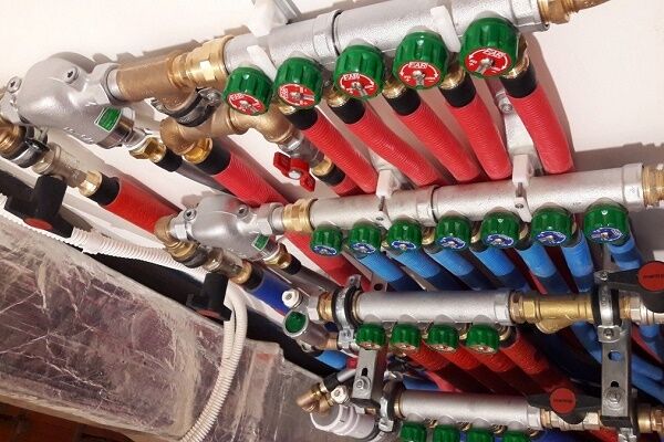
The basis of the collector heating scheme and the main working body is the distribution unit, commonly referred to as comb system.
This is a special type of plumbing fittings, which is designed to distribute coolant through independent rings and lines.
The collection group also includes: expansion tank, circulation pump And safety group devices.
The collector assembly for a two-pipe type heating system consists of two components:
- Input – it is connected to the heating unit through a supply pipe, takes over and distributes the coolant heated to the required temperature along the circuit.
- Day off – it is connected to the return pipes of independent circuits and is responsible for collecting cooled “return” water and redirecting it to the heating boiler.
The main difference between manifold heating wiring and the traditional series connection of devices is that each heating device in the house has an independent supply.
This design solution makes it possible to control the temperature of each battery in the house, and, if necessary, turn it off completely.
Often, when designing heating, a mixed type of wiring is used, in which several circuits are connected to the unit, each of which is controlled independently. But inside the circuit, the heating devices are connected in series.

Pros and cons of the collector-beam system
Among the undeniable advantages of installing a collector system, it is worth highlighting:
- Ease of use. Due to the fact that each element is controlled independently, the consumer has the opportunity to set the temperature anywhere in the house. And as needed, it’s easy to turn off one or a group of heating devices in the room. At the same time, the temperature in other rooms will remain the same.
- Ability to use small diameter pipes. Since each branch leading from the collector feeds only one device, small-diameter pipes that can be easily hidden in a screed can be used to lay it.
- Maintainability. If problems are detected, it will be easy to disconnect any section of the pipeline without interrupting the operation of the entire system.
To form several circuits with different parameters, for example: pressure drops or different media temperatures, distribution combs with a hydraulic compensator function are used.
The hydraulic arrow is a capacious pipe, to the outputs of which a number of circuits with independent circulation are connected.
The water heated by the boiler flows inside the hydraulic arrow. Circulating inside the device, water is taken at different distances from the taps and redistributed along the contours.

Due to the fact that the heated coolant delivers heat to the batteries with less loss, the efficiency of the system increases. This makes it possible to reduce the boiler power and thus save fuel consumption.
The heating system, the main element of which is the collector, is not without drawbacks.
These include:
- Pipe flow. When compared with a series connection, the pipe consumption when laying a collector system is two/three times higher. The difference in costs is determined by the size of the area involved.
- The need to use circulation pumps. The installation of independent circuits is not complete without the installation of circulation pumps. This entails additional costs.
The weak link of the collector system is its energy dependence. So even with the boiler running, in the event of a power outage, the pipes will remain cold. For this reason, such systems are not recommended for use in areas where power outages are common.

When laying contours in a floor screed, it is worth considering that any connection is a potential leak point.And if a defect occurs, the monolithic concrete will have to be opened to eliminate it. And this is already a very troublesome and costly undertaking.
Therefore, the connections of the collector system networks are located exclusively above the floor level. Most often they are confined to the manifold cabinet.
Principles of drawing up wiring diagrams
There are no uniform planning standards when drawing up wiring diagrams for a collector system. Equipment is selected for specific tasks.
But experts agree on one authoritative opinion that such a system is in no way suitable for heating apartments. This is due to the complexity of the project due to the fact that two or more risers are usually supplied to the residential premises.
And one of the prerequisites for the implementation of the scheme is the need to connect all batteries to one riser.
You may also find information about how to connect the heating radiator.

If you weld all the other water supply channels so that one riser takes on the entire load, a closed hydraulic circuit is formed within one apartment. All heating devices located higher up the riser will be cut off from the system and will not receive the desired heat.
Residents living above will sooner or later discover the reason for this phenomenon, and the scheme will have to be forcibly redone again, paying a considerable sum.
Manifold heating distribution can be installed in new apartment buildings, provided that additional valves were installed in them during the construction stage to connect circuits of various configurations.

The collector system is ideally suited for private homes.
The main thing is to adhere to the basic recommendations of professionals when designing the wiring:
- Availability of an air vent. The automated valve is placed directly on the supply and return manifolds.
- Availability of expansion tank. Its volume indicator must be at least 3% relative to the total volume of coolant. But it is also possible to use devices with a larger volume.
- Location of the expansion tank. It is installed on the “return”, placing it in front of the circulation pump along the flow of water. More details about its installation are described in our other article.
- Installation of circulation pumps on each circuit. Their location is unimportant, but due to the low operating temperature they exhibit maximum efficiency on the return line.
If it is necessary to use a comb equipped with a hydraulic compensator, an expansion tank is installed in front of the main pump, which is designed to ensure the movement of water in a small circuit.

The circulation pump is fixed so that the shaft is strictly horizontal. Otherwise, the very first air lock will leave the unit without lubrication and cooling.
You can read more about choosing a circulation pump In this article.
If there are additional distribution nodes in the heating system, they should not be communicating.
Selection of system components
When designing heating, it is best to purchase factory-made distribution units.
Thanks to the diversity of the range, it will not be difficult to select a comb for certain heating parameters, thereby ensuring the accuracy and reliability of the system.

The key parameters when choosing pipes for heating circuits are corrosion resistance, heat resistance and high burst strength. In addition, the pipes must have the necessary flexibility so that they can be laid at any angle.
When choosing products, preference should be given to pipes produced in coils. The use of one-piece products will allow you to avoid connections in the wiring, which is especially important for closed installation methods inside the screed.
Pipes for private cottage systems
When designing heating in private houses, it is worth focusing on the fact that the pressure in the system is about 1.5 atmospheres, and the coolant temperature can reach:
- for radiators - 50-70 degrees;
- for heated floors - 30-40 degrees.
For autonomous heating systems with their predictable parameters, it is not at all necessary to purchase stainless corrugated pipes. Many owners limit themselves to purchasing pipes made of cross-linked polyethylene marked “PEX”.

Such pipes are joined using tension fittings, so that inextricable connections can be obtained.
In addition to high performance parameters, the main advantage of cross-linked polyethylene is the mechanical memory of the material. Therefore, if you forcefully stretch the edge of the pipe and insert a fitting into the resulting gap, it will tightly surround it, ensuring a strong connection.
Using metal-plastic pipes The connection is made using union fittings with crimp nuts. And this already turns out to be a detachable connection, which, according to SNiP, cannot be “solidified”.
You may also have information about which pipes are best to choose for heating, reviewed here.
Pipes for apartment buildings
If the collector system is installed in an apartment building, then it is worth considering that the operating pressure in it is 10-15 atmospheres, and the coolant temperature can reach about 100-120 °C. It should be remembered that collector heating is only possible on the ground floor.
The best option for installing the system in an apartment building is the use of corrugated pipes made of stainless steel.
A clear example of this is the products of the Korean company Kofulso. Pipes of this brand are capable of operating at a working pressure of 15 atmospheres and withstand temperatures of about 110 °C. The collapse pressure of Kofulso pipes reaches 210 kgf/sq.cm.

Assembling pipeline connections using such elements is not difficult. The pipe is simply inserted into the fitting and secured by screwing on a nut, which compresses the corrugated metal surface with an elastic silicone seal.
System installation features
The collector heating system of a private house should be installed during the construction stage. After all, after laying or pouring the finished floor, installing such a system will become economically infeasible. The only solution to the problem in this case will be an open method of wiring installation.
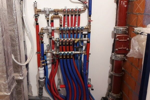
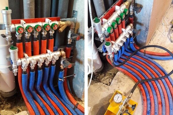
Installation of distribution comb
On the floors of houses with horizontal heating distribution, to accommodate the collector, circulation pump and control equipment, you will need to install a closed box - a collector cabinet.

The manifold cabinet is installed in separate niches of rooms protected from moisture. Most often, a place is allocated for this in the hallway, dressing room or pantry.
When designing the heating of a two-story building, it will be necessary to install two collector groups: on the first and second levels. Additional distribution units will ensure approximately the same length of the circuit.
As an option, you can take as a basis a scheme in which the first group will be responsible for the distribution of heat along individual circuits, and the second will act as a key component in arranging a “warm” floor.

The number of collector inputs and outputs is always equal to the number of heating elements located on the floor: radiators or underfloor heating rings. For each room, a separate branch is laid, which, by combining several heating devices, will implement a passing or dead-end circuit.
To reduce the cost of connecting radiators, a “pass-through” circuit is used.

With a “pass-through” system, several devices connected in series will be perceived as one element.
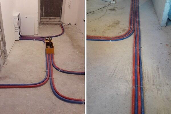
Pipeline laying options
When collecting pipes, the most commonly used method is laying pipes in a concrete screed. Its thickness varies between 50-80 mm, which is quite enough to “monolithize” the intra-house wiring of the heating system.
But according to SNiP, only unbreakable connections are allowed to be laid in concrete.

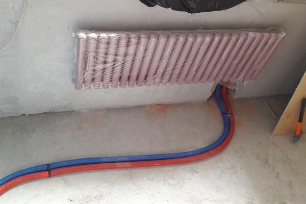
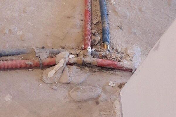
For this purpose, metal-plastic pipes with a diameter of 16 mm are often used. Due to the fact that they bend easily, it is convenient to lay the pipeline under the floor.
When planning to fill metal-plastic pipes with concrete screed after pressure testing of the system, it is necessary to first wrap them with thermal insulation.
Such a layer will minimize the risk of pipe damage due to thermal expansion, since in this case they will “rub” not against the concrete, but against the insulation.

Plywood is laid on top of the screed, which is covered with a finishing floor covering: linoleum or parquet.
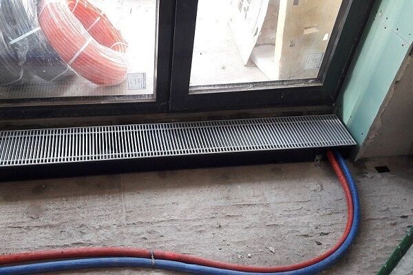
Pipes can also be connected to radiators from the side or from above, for example: in the space of a false ceiling.
Some craftsmen prefer to lay pipes externally, placing them along the walls and hiding them behind decorative skirting boards.But this method of installation entails an inevitable increase in the length of the pipeline.
It is not recommended to lay the pipeline through doorways. This can lead to the fact that when installing the threshold of an interior door, the pipe will be damaged at the time of drilling.
If the pipeline needs to be laid through a wall, in order to prevent its damage due to shrinkage of the building, the hole in the wall should be equipped with a sleeve.
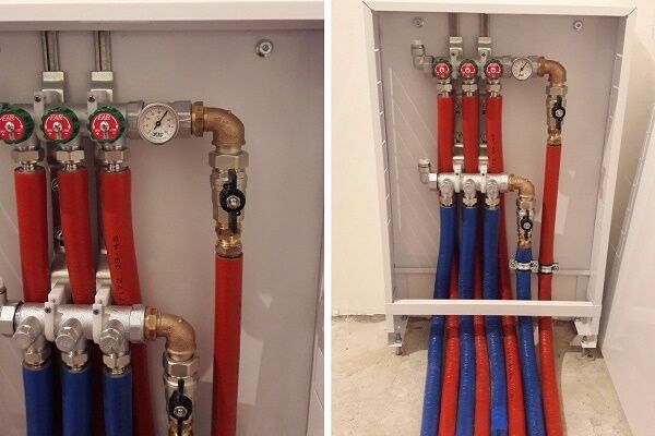
A separate shut-off valve is installed on each hydraulic circuit coming from the distribution comb.
To be able to bleed the air accumulated in the system, install:
- at the distribution center – air release valves;
- on radiators (accumulates at the highest points) – Mayevsky cranes.
Due to the fact that each hydraulic circuit coming after the collectors is an independent system, it is convenient to use when creating “warm floors”.

Air circulation when arranging the floor option occurs naturally.
When implementing such a system, metal-plastic pipes are laid on a heat-insulating pad, forming a pattern in the form of a snake or spiral. The diameter of the pipes and the laying pitch are determined according to calculations. One condition is that the length of one circuit should not exceed 90 meters.
The laid circuits are connected to the distribution unit, and after checking the tightness of the connections, they are filled with concrete mortar. The height of the screed is 70-90 mm.
The same principle is used to install both the collector system of a two-story cottage and a residential building with a large number of floors.
Conclusions and useful video on the topic
System design principle:
How to install correctly:
By installing a collector heating system in your home, you will have the opportunity to individually configure the operating modes of the devices.
And the additional costs of increasing the length of the pipes are compensated by reducing their diameter and simplifying the installation of the system.
Do you have a manifold heating system at home? Or are you just planning to equip it, and are you currently studying the information? Maybe you have a question about drawing up a wiring diagram for the collector system? Ask your questions, share your personal experience of arranging heating in your home by leaving comments under this article.


In a large house, collector wiring is just right. There is no need for dancing with tambourines or setting up the system, there are no complaints about cold radiators at distant points.
True, many customers are opposed to collectors, purely for reasons of economy. Still, assembling this thing costs a lot of money, in any case, much more expensive than conventional wiring. We have to select budget collectors; many manufacturers now produce them.
Well, and convince people that it will be better and more comfortable this way. And the fact that there is an electric pump there means that in a large house, especially outside the city, you cannot do without a generator.