How to connect a telephone socket: connection diagram and installation rules
Despite the rapid decline in the popularity of landline telephones, there are not so many people who are ready to refuse them outright.Admit it, it happens that it is sometimes extremely difficult or even impossible to do without a traditional connection.
To connect the device to the switching network, you need a low-current node, the installation of which can be done by yourself. We will tell you in detail how to connect a telephone socket without calling a technician.
There is absolutely nothing complicated in the schemes and methods, and the useful information we offer, as well as photos and videos, will help you understand the issue.
The content of the article:
Design features of a telephone socket
The designs of landline telephones are modified and improved every year. And modern devices are significantly superior to their predecessors, standing out favorably with their high reliability and ease of use.
To ensure uninterrupted operation of the device, two conditions are necessary:
- Availability of an active communication line from the PBX.
- Possibility of electrical connection of a stationary device to this line.
The only thing that does not change in the field of telephony is the principle of operation of landline phones. However, there are significant changes in designs and connection methods.
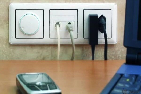
Old and new telephone switching options are presented in the photo selection:
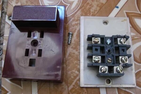
Despite the differences in design and connection methods, any telephone socket traditionally includes three main elements:
- Frame – made of dielectric material (ceramics or plastic).
- Contacts – spring-loaded brass elements that ensure reliable passage of currents through the electrical circuit.
- Terminals – adapters necessary for connecting wires.
The electrical contact sockets of the stationary socket are recessed into the housing. This solution allows you to protect the device from accidental short circuits.
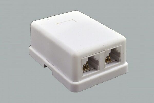
There are single and multi-connector models on sale. The first ones are designed to connect one device, the second ones allow you to switch several devices at once.

Old and modern device standards
As equipment has improved, the way phones connect to the communications network has undergone a number of changes. In the first models of telephones, connection to the communication line was carried out without the use of sockets at all.
To create a closed current loop, the wires were simply twisted together or connected by any other available means.
In the 80s of the last century, connections between telephone exchange lines were made using two-core copper wires. And to ensure a quick-disconnect connection to the telephone, sockets and plugs of the RTShK-4 standard were used. This abbreviation stands for "four pin telephone socket."

The RTShK-4 design includes a key and two pairs of contacts.The first pair ensures the phone operates in normal mode, the second pair allows you to connect an additional line, provided that both devices are on the same phone number.
As a result of the widespread dissemination of microprocessor technologies, Registered Jack equipment marked “RJ” began to be actively used to replace obsolete models of the RTShK-4 standard. It complies with the international standard IEC 60884-1 and 60669-1.

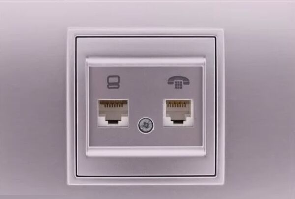
Connection of modern landline telephone models for use at the household level is carried out through sockets equipped with one pair of contacts. The housings of such devices are mounted in the cavity of a plastic module and are marked with RJ-11 symbols.
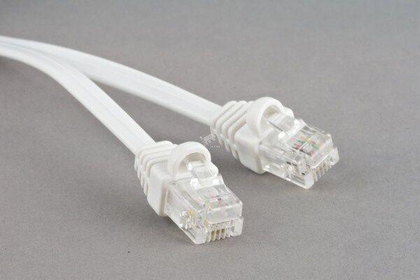
Between the two contacts, which are compact metal plugs, the cores of the supply wire are buried. Models of the RJ-11 standard are recommended for connecting devices to linear telephone lines.

To connect two devices to separate lines and create office mini-PBXs, RJ-12 and RJ-14 standard devices are used. Universal four-wire connectors are suitable for most models of telephone equipment.
To connect several devices at once, you just need to assemble the sockets sequentially into blocks, while observing the diagram: the first line is connected to contacts No. 2 and No. 3, and the second - to No. 1 and No. 4.Devices of this series are mostly used to create mini-PBXs when arranging office premises.

Installing an adapter allows you to connect plugs of both old and new standards with lines equipped with modern technologies.
The main difference between RJ-25 standard devices is three pairs of working contacts. For this reason, the connection of such equipment can only be carried out by a qualified specialist who is well versed in telephony and electrical issues.

At connecting computer systems, faxes, modems and other complex communication devices also use the RJ-45 standard. When connecting devices RJ-45 standard The main attention is paid to the matching of plastic keys.
Despite the design differences between the old and new standards, the device plugs have similar connectors and dimensions. The device is connected to the network only through two contacts. Only modern models use only middle contacts.
For those wishing to familiarize themselves with the connection features, the photo gallery will help:
Installation diagrams and connection methods
Connecting a telephone socket is much simpler than its electrical counterpart. But a process that involves working with, albeit low, but still voltage, requires accuracy and caution.

When installing a telephone socket, you can use one of two installation methods:
- open - involves installation in an overhead manner;
- closed - in which the telephone line is hidden inside the wall.
When choosing a laying method, they are guided by the design of the walls, the service conditions of the communication line and the pretentiousness of the design of the room itself. Surface-mounted sockets do not look very aesthetically pleasing, but they are ideal for speed of maintenance: in a matter of minutes they can be removed from the support and the integrity of the contacts can be assessed.

To protect exposed wires from mechanical damage, decorative plastic cable channels are used. They are found on sale in the form of wall structures and floor skirting boards.It is convenient to monitor the condition of the wire in them through one- or two-sided snap panels.
For closed installation, KSPV cable is most often used. The single core of this cable is made of copper wire, and the outer sheath is made of polyethylene, painted white.
The telephone line is also laid using the TRP distribution cable. It has a dividing base. The core of this single-pair wire is also made of copper and insulated with polyethylene.

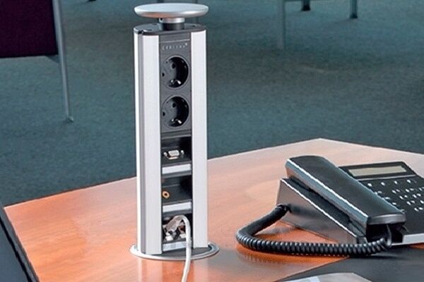
To decorate the connection points and make them less noticeable to prying eyes, the devices are placed behind TV screens and monitors, and are also built behind the façade of wall-mounted furniture.
A separate line should be highlighted for sockets built into the baseboard. The main thing is to choose models whose front panel fits tightly to the surface of the baseboard. Otherwise, over time, it will begin to move away from the base, exposing unsightly seams.
How to connect a telephone socket
When installing a telephone socket, it should be taken into account that the voltage for low-current communication devices does not exceed 60 Volts. But even reduced voltage can still create a current, causing discomfort to a person.
At the moment when a call occurs over the telephone line, the voltage completely rises to 110-120 Volts. And it can cause serious pain upon contact. It drops to a value of 12 Volts only after removing the handset.

The principle of placement and method of installing telephone sockets is practically no different from the technology for installing electrical sockets. Since today the most common devices are those that have the J-11 and J-12 standards, we will consider the intricacies of connecting a telephone jack using their example.
Stage #1: Preparatory work
The first thing you need to do is study internal communication patterns. They are included with the product instructions.
There should be no problems when connecting the J-11 and J-12 standards: you just need to connect the wires of the appropriate polarity. The main thing is that in the plug suitable for the device, the wires are routed in a mirror image of the contacts of the socket.
If you unknowingly purchased and plan to install the J-25 standard, the design of which involves 6 contacts, use only the 3rd and 4th contacts for connection.

When planning to use an old standard device, you should worry about purchasing a universal socket in advance. It is equipped with a four-pin connector and connector. In addition to the socket itself, it is also necessary to prepare a two-core wire with a cross-section of 0.3-0.5 mm.
It is necessary to determine and outline the location in advance and installation height.
The following tools need to be prepared for the work:
- building level;
- cross knife;
- voltmeter;
- screwdriver;
- wire cutters;
- graphite pencil;
- protective gloves;
- Double-sided tape;
- hammer drill (if installing a new point).
When choosing a screwdriver, you are guided by the type of surface and dimensions of the screws used for fastening. To minimize the likelihood of electric shock, it is better to perform all manipulations with a screwdriver whose handle is insulated.

To connect a hidden type socket, you must first make a hole in the wall for its installation - socket box. This can be done using a hammer drill equipped with a special crown with a diameter of 60-70 mm.
In the absence of one, the work can be done with an ordinary hammer and chisel. But manual labor will take much more time and effort. Then, to the hole made, it is necessary to drill a channel for laying the telephone cable.
There are certain nuances when installing a socket box in plasterboard wall.
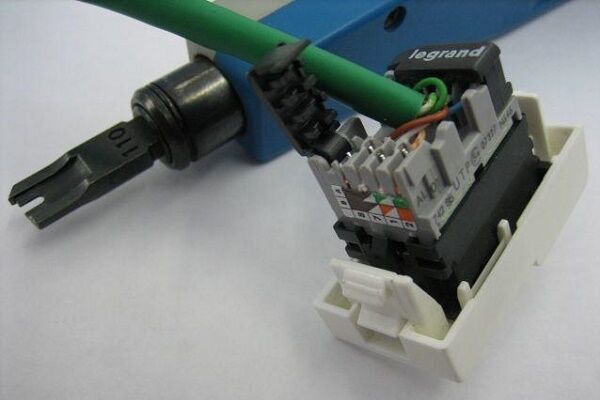
Stage #2: Stripping the ends of the cores
Before you start melting the wires, you need to strip the ends of the wires, removing the outer layer. Just expose the outermost 4 cm of the wire.
When stripping a telephone cable, remember that it is very vulnerable to damage. And broken wires will only lead to equipment malfunction. Therefore, it is important to use specialized stripping tool.
Since it is not always possible to carry out the cutting accurately the first time, experienced craftsmen recommend that when laying the cable, make some allowance for its length. The excess wire can then be hidden under the cover of the device.

The technician’s task is to strip the ends of the wires from the braid so that when exposed they are intact and free of any defects.
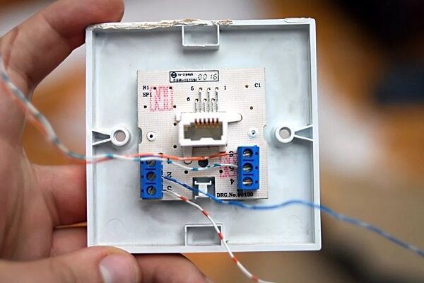
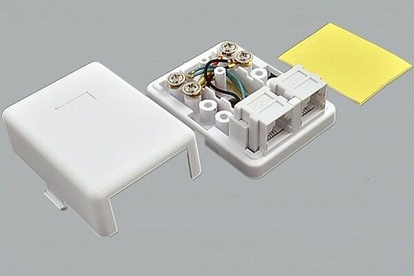
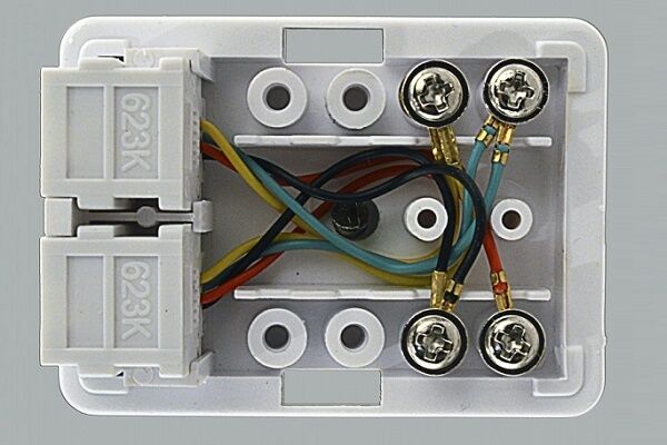
Step #3: Connecting the outlet wires
Stripped wires with separated cores are connected to the connectors of the box itself, focusing on the markings indicated on the front panel of the indoor unit. With a closed installation method, for ease of connection, the wires are made to protrude beyond the wall plane by 50-80 mm.
Experts recommend checking the polarity of the contacts when connecting wires using a tester.

If the rules regarding polarity are not followed, there is a high risk that the telephone will malfunction from time to time during operation.
At this stage of work you will need a voltmeter. With its help you need to check the readiness of the communication line. The line voltage should be between 40-60 Volts.
The supplied cable cores are applied to the clamp and tightened tightly with special screws, ensuring reliable fixation. The shape of the grooves to which the cores are attached facilitates the installation process. There is no need to wrap the joints with electrical tape.

When performing open mounting, at the final stage all that remains is to close the housing cover using the latch and secure it with screws.The finished socket is attached to the wall or floor, “planting” it with double-sided tape.
With a closed installation method, making sure that the wires are not intertwined in the socket box, according to the markings applied, the indoor unit is mounted into the wall. Having given the block the desired position, the structure is fixed using expansion screws and self-tapping screws.
At the final stage, all that remains is to eliminate the gaps between the socket box and the wall, covering it with gypsum mortar, and also seal the channels with the laid telephone cable.
After the plaster has acquired the desired strength, the protective edging is installed in place and the front panel is attached. In modern devices, the protective edging is snapped onto the internal unit, and the front panel is secured by screwing in screws.
If you need to connect a multi-socket outlet that allows you to install several telephone sets, you must adhere to the same technology as when installing the classic version of the device. The only difference in the process is the increase in the number of conductors requiring connection.
Conclusions and useful video on the topic
Device Connection Guide:
Replacing an old socket with a combined connector RTShK-4 and RG-11 with a similar new device:
There is nothing difficult about connecting a telephone socket. The only thing is that you should not save money by purchasing equipment in a low price range. It does not always meet the standards and can fail even at the connection stage.
Share your personal experience of connecting a telephone socket, leave comments on the article and ask questions. The contact form is located below.


Of course, we need to slowly move away from old-style sockets and switch to new ones. By the way, in general it is more promising to even make general wiring for RJ 45. At least this way the functionality of the wiring will increase. I also highly recommend buying a normal crossing tool before installing new sockets. As a result, not only will the work be completed faster, but the contacts will also be made more reliably.
I connected my first telephone socket at random. I was using a screwdriver then, and I’m amazed at how miraculously everything was holding together. And then the renovation started, everything had to be installed beautifully. I did everything approximately as you wrote. I didn’t pay attention to polarity in both the first and second cases, and I didn’t have a tester at hand. So I, an ignoramus, still didn’t know where the “minus” was and where the “plus” was.
It’s still not clear how to connect 2 phones to one socket so that when you pick up the handset of one phone, only beeps are heard in the second phone.
Good afternoon, Aristarchus. The article does not address such a question. For parallel telephones located in different apartments (the situation of the last century, when communications were the property of privileged people), blockers were used.
The device allowed for alternating conversations - subscriber “A” talked, for example, with caller “B”, and subscriber “C” waited for the end of the conversation to call “D”. Sometimes people would scandalize: “I should have called urgently, but you organized a press conference.”
I won’t describe the operation of the blocker - I’ve just attached a screenshot of the diagram with an explanation. There were other device options that expanded the capabilities of the PBX.
Two-core wire, one large, one small, how to connect to a telephone socket?
Tell me how to connect the wires of the Lexman First (Rj11) telephone wall socket, the plastic transparent cover folds back? I'm afraid to break it if it's not so