Connecting a double switch: standards and diagrams + installation instructions
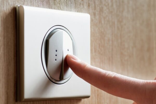
Convenient two-key switches, due to the increase in functional load, are superior to single-key analogues.If, instead of ordinary single electrical installation devices, you equip your house with double devices, the savings will be significant.
The double switch must be connected in compliance with safety standards and regulations.
In this material we will tell you how a double switch works, name the advantages of such devices, and also provide detailed installation and connection instructions.
The content of the article:
How does a double switch work?
You can’t connect any device correctly without first studying its “stuffing” and operating principle. In this sense, switches are not particularly difficult.
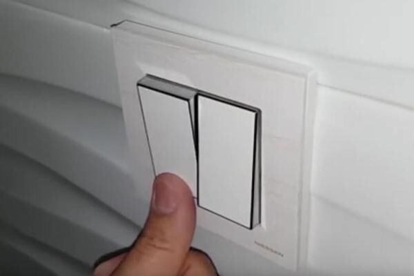
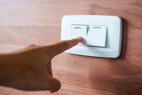
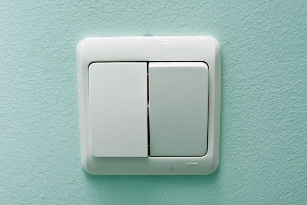
The design of two-key models follows the design of single-key models, but differs in the number of terminals and connection principle. The external difference is reflected in the name of the model - it has two separate keys, each of which controls an electrical circuit.

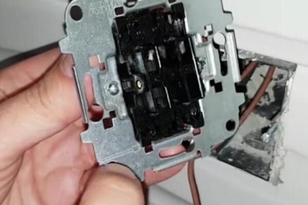
Metal and plastic parts are used in the manufacture of devices. In particular, conductive metals - steel and copper - are used for contacts.
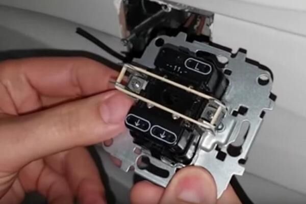
To better examine the individual elements of the switch, let’s figure out how disassembly and connection.
The symbols for which numbers and Latin letters are used may differ on different models. For example, L may indicate the common supply phase, while the numbers 1,2 indicate the outgoing phases. Arrows can also be used to indicate input and output.
Advantages of two-key models
Why is it worth abandoning the usual and easy-to-use single-key instruments for the sake of double ones?
In fact, the advantages are obvious:
- from one device you can control two different lighting fixtures or two groups of lamps;
- the light intensity in the room can be adjusted, depending on the number of light sources involved;
- due to the selective switching on of individual lamps, energy savings occur;
- if desired, you can control the lighting mode in two rooms at once (in the kitchen and hallway, in the bathroom and toilet);
- Electrical wires are used more rationally and economically.
Adjusting the light is the ability to create a comfortable environment for performing certain actions. For example, when working or reading, you can use both keys to turn on all 5-6 chandelier lights. And for relaxation, 1-2 light bulbs are enough, creating diffused, dim lighting.
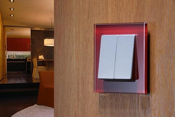
Another advantage of modern models is their different designs. Thanks to the variety of colors and styles, you can choose a device that best suits the appearance of the room.
Like single-keyboards, double models come in built-in and overhead types.If the walls in an apartment/house are made of brick, concrete, aerated concrete or plasterboard, internal switches are usually installed.
Installation of overhead devices is typical for wooden houses, where when installing internal wiring, certain difficulties associated with PUE standards are expected.
Popular circuit solutions
When choosing a double switch connection diagram, two related factors should be taken into account:
- what grounding system is used in the house - TN-C or TN-S;
- one or two lighting fixtures controlled by a switch.
TN-C is considered an obsolete grounding system. The peculiarity of installing the switch is that it receives only two wires from the electrical panel instead of three.

Newly built houses use the modern TN-S system. Before you connect the double switch yourself, you must make sure that a three-core wire is stretched from the machine to the mounting location of the electrical installation.
Let's compare the difference in connection.

The presence of the third grounding conductor does not in any way affect the connection of the wires in the switch mechanism: only phase wires remain there, one incoming and two outgoing.
If lighting devices controlled from one switch are located in different rooms, the circuit will differ only in the routing of the conductors in different directions.Let's consider a scheme in which one group of lamps is in the room, the second in the corridor.

If the machine is connected with a three-wire wire, then the ground is connected to the grounding conductors of groups of lamps and, like zero, is separated in two directions.

The appearance of the third grounding conductor does not fundamentally change the circuit: it extends from the circuit breaker in the panel and is connected to the ground of two groups of lamps in the distribution box.
The distribution of lamps from one chandelier into groups can occur in different ways, depending on the requirements for lighting intensity. The five-arm device can be divided in two ways: 4 + 1, 2 + 3.
The number of options for connecting a six-arm chandelier increases: 1 + 5, 2 + 4, 3 + 3. That is, the more lamps in the lighting fixture, the more options for combining them into groups.
Installation and connection instructions
The connection process can last 15 minutes if a simple replacement of an old device is required, or several days if there is a need to install new wiring.
Selection of materials and tool preparation
If a house/apartment is being renovated, they try to replace the old aluminum wires with copper wires, which are superior in all respects. This is also regulated by the PUE standards.

The wires must be laid either horizontally under the ceiling, or strictly vertically down to the installation site. This will prevent accidental cable breaks during subsequent repairs.
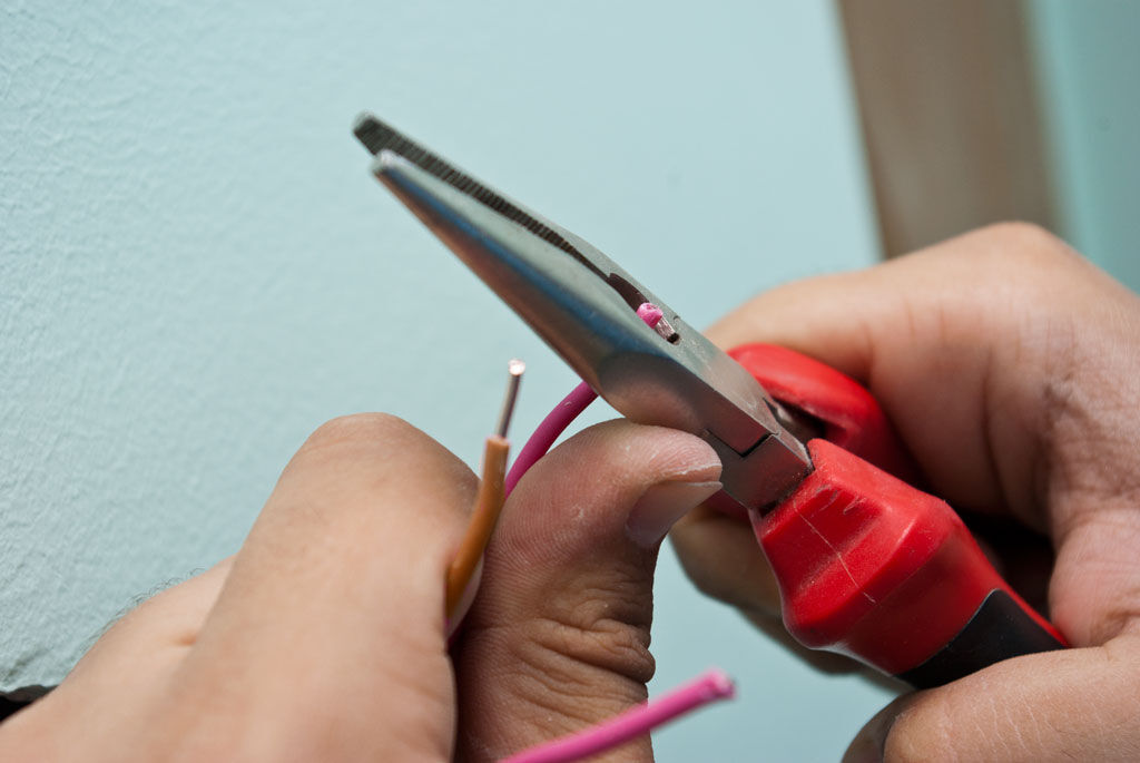
To work with electrical installations, you will need hand tools with insulated handles:
- universal screwdriver;
- round nose pliers;
- pliers;
- construction or stationery knife;
- indicator screwdriver.
Marking material and insulated protective gloves will also come in handy.

The switch is chosen based on the interior design. When purchasing a new cable, take into account the system load. Lighting groups are among the lowest-power sections of the network, so a VVG 1.5 mm² cable is suitable, or better yet a VVGng cable with polymer protection of reduced flammability.
Cable counting is carried out using a tape measure. To the total length of the wires, you need to add a reserve for twisting in junction boxes and installation in terminals. Read more about calculating cable cross-section in this material.
About connecting electrical wires in the distribution box
The first stage is connecting the cable to the machine, which is located in the electrical panel:
- working core (red or brown) - to the terminal of the circuit breaker;
- zero (syn.) – to the zero bus;
- grounding (green or yellow-green) – to the grounding bus.
It is recommended to delegate work with automatic devices located on the switchboard to electricians who are responsible for the condition of the general house network.It is prohibited to make any changes to the electrical panel yourself. We also recommend reading the article where we examined in detail the color coding of electrical wires. More details - go to link.
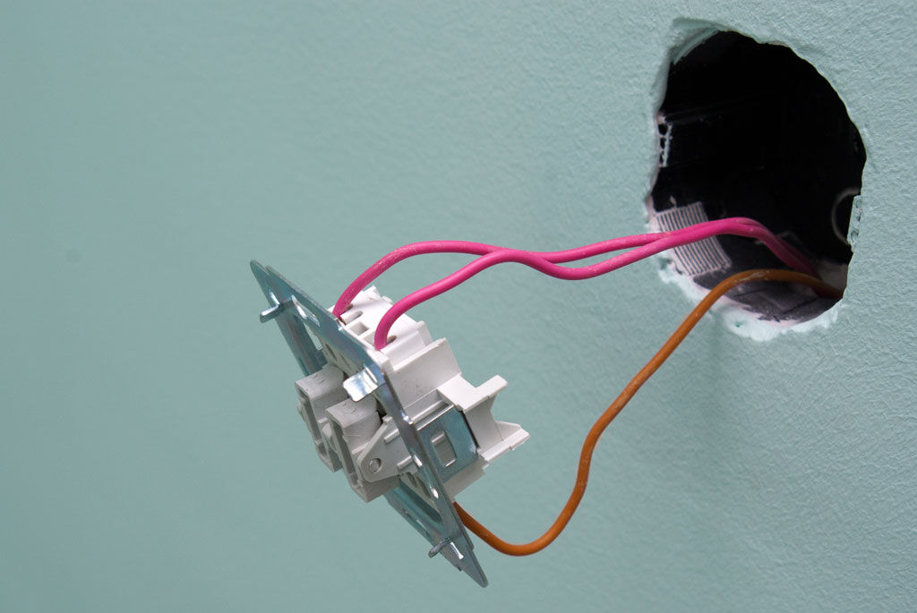
From the switchboard the wire is pulled to the junction box, and from it to the switch and lighting fixture or to two devices/groups. It is very important not to confuse wire connection in the junction box.

As a result, five connections need to be made in the junction box. To do this, use twisting, soldering or a more modern method - terminal boxes.
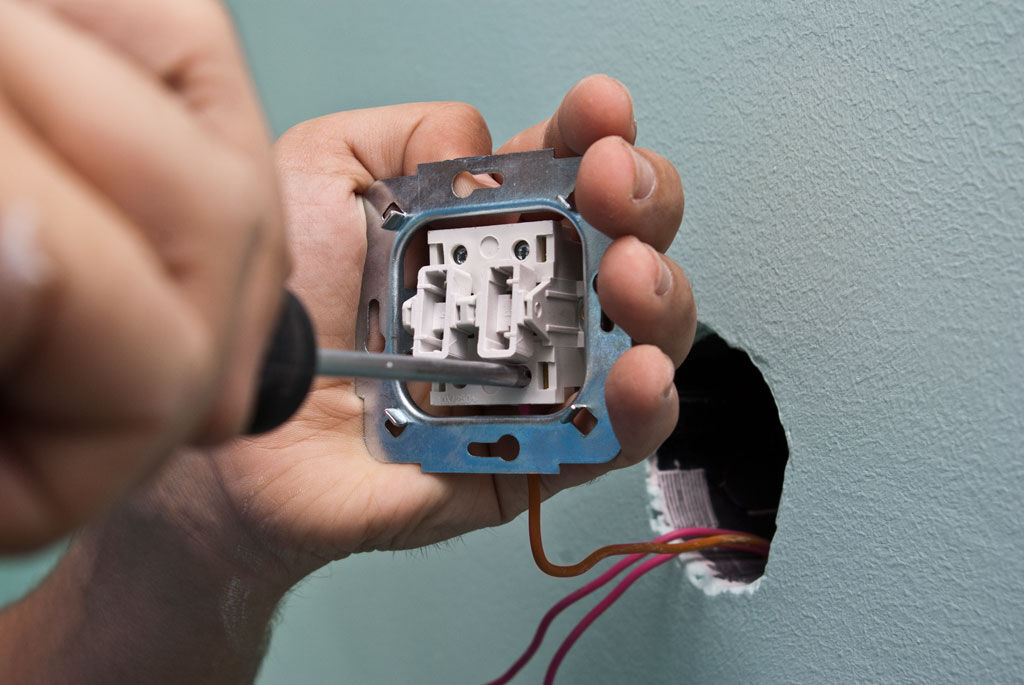
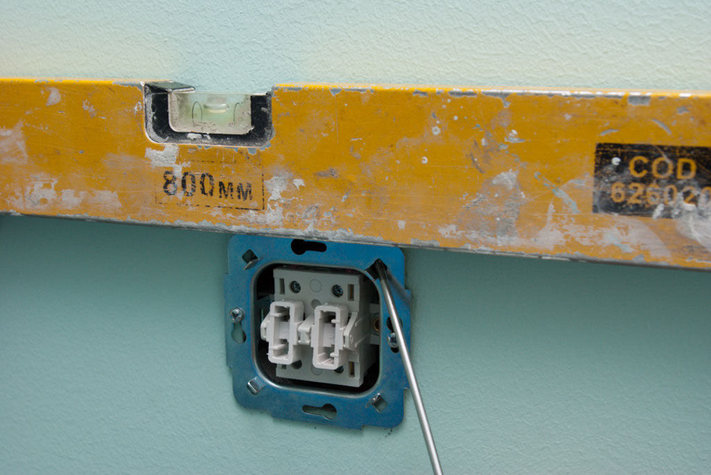
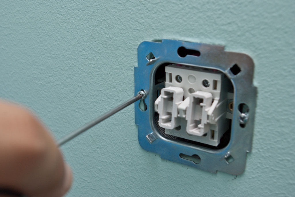
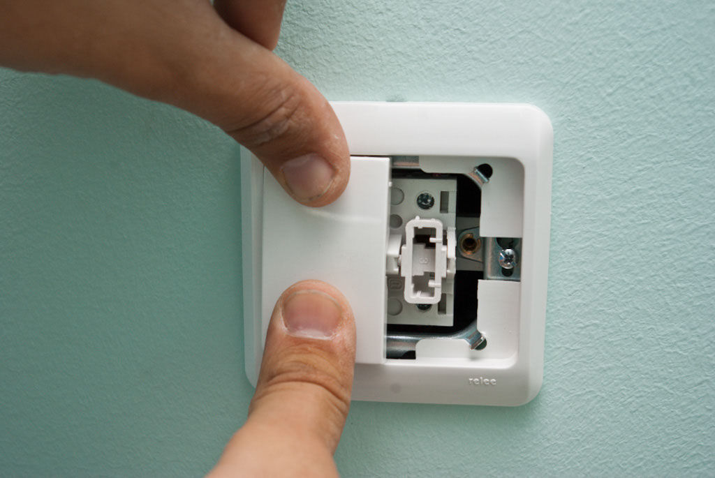
The procedure for installing the switch on the wall
The switch can be mounted in two ways: in a special installation box (socket box) or directly in the wall. The second method is preferable if the device is mounted in a plasterboard partition. Let's look at step-by-step instructions on how to connect and install a double switch yourself.
Before installing the DV, it is necessary to connect all lighting fixtures from the operating circuit: one chandelier, a chandelier with a group of spotlights, or lamps in different rooms. Without the initial installation of the luminaires, it is impossible to correctly check the operation of the switch.
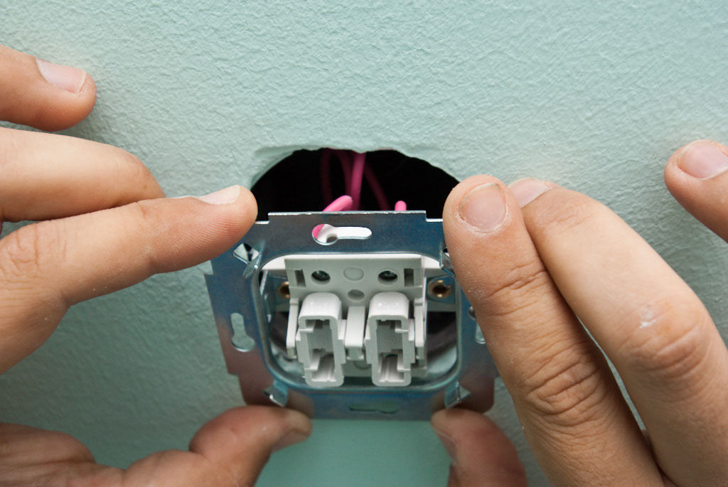
It is possible that the lights will not light up. You will have to re-disassemble the switch and make sure that the wires are inserted into the correct terminals. The reason may also lie in the incorrect connection of the wires in the junction box - you will have to look into it too.
A detailed connection diagram for a two-key switch is discussed in this article.
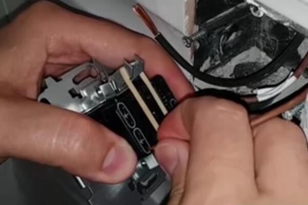
To make it easier to determine the working function of each wire in the future, the wires are marked during installation.
Don't forget about safety
Any manipulations with electrical installations should begin by turning off the circuit breaker, which is located on the communal switchboard. After this, the presence of voltage in the network is checked again with an indicator screwdriver or tester - and so on each time before you start working with the wires.
If the switchboard is located on the landing, then during the work it is recommended to hang a warning sign so that someone does not accidentally turn the toggle switch.

Protective gloves with insulation can also protect against electric shock, although they are not very comfortable when working with wires. During gating and plastering of walls It is better to use work clothes, comfortable shoes and a mask or respirator to protect your lungs from dust.
Conclusions and useful video on the topic
Interesting information about ways to connect wires, install a switch, and connect devices will add to your knowledge about home electrical installation.
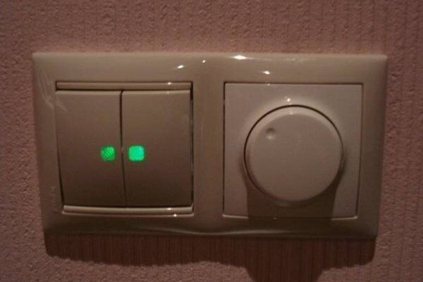
The nuances of connecting an electrical appliance with backlight:
Details about connecting wires in the junction box:
Connecting a chandelier using soldering:
From choosing a location to connecting to the machine:
Having experience in working with electrical wiring, you can easily cope with the installation of a two-button switch - the main thing is not to make a mistake in choosing a circuit and install reliable wires.However, if you have any doubts regarding the connection or connection of the cores, it is better to seek help from a professional electrician or carry out all actions under his supervision.
Do you have practical skills in connecting two-key switches? Or have questions about the topic of the article? Please ask them in the comments section, and we will try to answer them promptly.


When installing switches, including two-gang switches, you can avoid the use of distribution boxes. According to the PUE, the junction box must be accessible for maintenance, but in the conditions of modern repair this is oh so difficult to do. We proceed in a simpler way: we bring all the same wires into the socket box to the switch as in the distribution box, and we carry out the wiring directly in the socket box behind the switch mechanism. And the wolves are fed, and the sheep are safe!
Good afternoon, Dmitry. Modern renovations that make distribution boxes inaccessible are nonsense. No one forces you to wall up distribution boxes under the thickness of the plaster. Install them so that the covers are flush with the finish - you need to open them, cut the wallpaper crosswise and open the cover. I have attached a photo of such an opened box. The finish, as you can see, has not been damaged.
The generally accepted sub-ceiling main electrical wiring allows you to quickly install additional boxes and make branches for additionally appearing lamps and sockets.