Internal water supply and sewerage of buildings: standards, norms and requirements
Communications are integral components of modern house-building projects.Whether it is municipal property designed for mass occupancy, or a private building for one family, internal plumbing and sewerage are carried out taking into account established norms and rules.
The same requirements apply to business facilities, as they apply to building structures for various purposes, the height of which is within 75 meters.
Agree, without knowledge of building codes it is impossible to competently design communication networks. In this article we have collected the basic requirements and standards for the installation of internal water supply and sewerage systems. This information will be useful when organizing new utility networks or reconstructing old lines.
The content of the article:
General rules for installing water supply systems
The supply of buildings (structures) with cold water is carried out from centralized or local sources. In this case, the choice of source for internal water supply is made based on the requirements of hygienic sanitation and fire safety standards.
For business, production technology requirements are added. In any case, the existing external water supply system is taken into account.

Hot water supply (DHW) is most often arranged according to the principle of a closed water supply, when hot water is obtained from heat exchangers or water heaters.
Standard hot water temperature range for residential premises:
- +60°С - bottom line;
- +75°С - the top indicator.
At the design stage, it is possible to provide for a DHW device with the possibility of supply from the heating network - the principle of open water supply.
In general, based on the purpose of the facility, the installation of the following water supply systems is provided:
- household and drinking;
- hot water;
- fire department;
- negotiable;
- industrial purposes.
In most cases, fire-fighting water supply systems can be combined into a single system with household and drinking (industrial) water supply systems, if any are included in the structure of the facility.
But the domestic drinking water supply is prohibited from being combined with networks transporting water whose quality does not meet drinking standards in accordance with SanPiN 2.1.4.1074.
Schemes of internal networks of hot water supply and hot water supply
Internal cold water, hot water, industrial or fire water supply systems are organized taking into account the inclusion of the following modules and elements in the diagram:
- inputs into the building;
- consumption metering systems;
- distribution lines;
- technological risers;
- technological leads;
- shut-off valves.
Based on the specific conditions of the location of residential buildings or technical facilities, it is permissible to organize storage tanks in the internal water supply system - hydraulic accumulators.

Circulation schemes should be provided at the points of hot water supply (during the period of absence), if there is a need to continuously maintain the temperature within the limits established by the standard within 60-75°C.
In this case, it is prohibited to connect water distribution units directly to the pipelines of the circulation system. Pressure losses in circulation circuits are not allowed to exceed 10% of the pressure value in other areas.

Standard for the maximum permissible value water pressure inside the drinking water supply is 0.45 MPa (4.5 atm.) at the point of the plumbing fixture located at a level lower than all others existing in the circuit.
The pressure at the points of plumbing fixtures located above all others must correspond to the rated values of these fixtures. In the absence of a document, they are guided by the lower limit - 0.2 MPa (2.0 atm.).
If the pressure exceeds the specified standards, it is necessary to provide installation pressure reducer or similar devices capable of reducing water pressure to normal values.
These devices must provide calculated pressure standards in static and dynamic operating modes of the drinking water supply system. It is also allowed to use shut-off valves equipped with built-in flow regulators - water meters.
Materials taken for installation and wiring of internal water supply systems, including fittings, pipes and equipment, must comply with the requirements of sanitary and epidemiological standards, national standards, SNiP.
Drinking water lines may be built and put into operation only after passing a sanitary and epidemiological examination and obtaining the appropriate permits and certificates.
Communications installation in a country house
Equipping a country house with communications the technological methods and principles are similar to the arrangement of a city apartment. The only difference is that water supply and wastewater systems for a private property must take into account the possibility of conservation.
This circumstance is provided for in the design, regardless of whether the house is connected to centralized networks or for it on the site independent water intake installed and a local sewage treatment point has been installed - a septic tank or VOC.
Construction of water supply networks
The process of constructing hot water supply/hot water supply systems must include the installation of check valves, provided that more than one input is created in a section of the internal water supply network.
The horizontal distance between the water supply inlet with a diameter of up to 200 mm and the sewerage system outlet (according to established standards) is at least 1.5 m. If the inlet is made of a pipe with a diameter of more than 200 mm, the standard for the horizontal distance to the sewerage outlet increases to 3 m.
During installation, it is necessary to place stops in places where pipelines turn (along horizontal and vertical axes), if mechanical stresses are not compensated by the connection diagram.

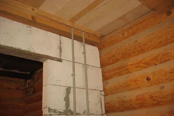
The rules establish that hot water/hot water distribution lines for residential building projects are installed in the following areas:
- in basements;
- in attics;
- under the floor - subject to removable covering;
- under the ceiling of non-residential premises;
- on technical floors;
- in the underground.
The passage in the wall of the building at the point of its intersection with the input pipeline is made with a gap of at least 200 mm from the surface of the pipe to the elements of building structures. After installation, the hole is sealed with elastic water- and gas-impermeable material. This installation is intended for dry soil. On wet soils, seals are installed instead of sealing.
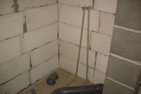
Hidden and open pipe laying
Riser pipes and inlets for hot water supply/hot water supply, metering devices, shut-off valves, control modules are located in communication shafts, in technical cabinets specially designed for such purposes.
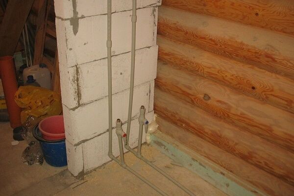
It is required to provide free access to technical cabinets. Open laying of risers and wiring is allowed along the walls of kitchen premises, shower rooms, toilet rooms, taking into account the placement of shut-off valves, as well as control devices.

If used polymer water pipes, then a hidden type gasket is provided. The exception is the lines of sanitary facilities. But it is prohibited to covertly lay steel pipelines with threaded connections without creating conditions for free access to these connections.
According to the requirements, lines are laid with a slope of at least 2 mm per meter of length. With appropriate justification, this norm can be reduced to 1 mm.

Cold water supply, designed for year-round operation, is installed indoors, where the minimum temperature is +2°C. If such conditions cannot be created, then installation is carried out to protect the pipes from freezing - additional heating is installed, for example, install the heating cable.
Thermal insulation of pipeline sections located in areas of short-term temperature drop to 0°C and below is mandatory. The same requirements are relevant for lines located at entrance doors or in other places in contact with outside air.
Removing air from the system
The DHW pipeline diagram must include the installation of air vents and vents. Air exhaust devices should be installed in areas located at a maximum height relative to the entire circuit.
Instead of air vents, it is allowed to use water fittings, also installed in high-altitude areas. Drainage devices are installed at the lowest points of the diagram, unless installation at the same low points of water fittings is provided.

The development of each hot water supply project should include measures aimed at compensating for deformations of water pipes that inevitably arise during changes in water temperature. The hot water pipeline diagram is designed for a fluid speed of no higher than 1.5 m/s.
Design decisions must take into account the service life of pipes and parts of hot/cold water supply circuits.
Regulatory data:
- at least 50 years — under operating temperature conditions up to 20ºС;
- at least 25 years — at temperatures up to 75ºС.
These standards take into account hydraulic resistance, the value of which must remain unchanged during the specified periods.
Water consumption measurement
Buildings equipped with cold water/hot water supply systems must be equipped water metering stations. Measuring equipment is installed at the cold water/hot water supply points in each building or apartment. The rules also require the installation of meters on pipeline branches that are directed to any non-residential attached premises.

On hot water supply lines with water temperatures up to 90°C, it is required to install measuring equipment on the supply and circulation pipelines. In this case, the circulation pipeline is additionally equipped with a check valve.
As you move in the area in front of the meter, you need to turn on filters - mechanical or magnetic-mechanical. Filter elements should be installed taking into account the permissible pressure loss of no more than 50%.
At the cold water supply input, the meters are installed in rooms where there is easy free access, where there is artificial or natural lighting, and the ambient temperature does not fall below 5°C.
Meanwhile, it is recommended to install measuring instruments for hot/cold water consumption in a single place.Installation of devices should provide convenient free access for reading information.
Water meters are installed on stands or brackets. The rules require that meters be protected from vibrations and mechanical stress transmitted by pipelines.
If there are no conditions for placing meters indoors, it is allowed to install them outside buildings, inside special wells. In this case, the device must be designed for operation in a flooded state.

The rules allow installation on vertical or inclined areas, if such installation is permissible according to the device passport. For placement on vertical sections of pipelines in residential premises, it is allowed to install meters from class “A” group.
The circuit wiring of the meters provides for:
- turning on the taps on both sides of the device;
- creation of straight sections pipes on both sides of the device;
- creation of a bypass line - only for cold water supply.
All installed meters, as well as shut-off valves (when open) must be sealed.
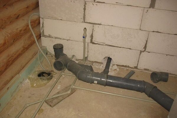
Arrangement of internal sewerage
Based on the purpose of the building, the construction of internal sewerage is provided:
- sanitary — collection and disposal of household liquids coming from plumbing household appliances (sinks, toilets, bathtubs, etc.);
- production — collection and disposal of industrial wastewater;
- drainage — collection and disposal of precipitation products.
Internal domestic sewerage is characterized by the installation of gravity pipelines, usually closed.

Industrial wastewater can be discharged through open tray systems if the wastewater does not emit harmful gases, vapors or leave unpleasant odors. It is recommended to lay sections of any sewerage system strictly straight with a given slope.
Standards for laying and installing lines
Outlet pipelines are connected to risers using oblique crosses and tees. If drain pipes from several plumbing fixtures located at the same level are connected, only oblique crosses should be used.
It is not permissible to use straight crosses for drainage, provided they are placed along a horizontal axis.
Non-pressure (pressure) internal sewerage lines must be made using pipes and fittings with a service life of at least 25 years. Technical fittings must ensure stability of hydraulic resistance throughout the entire service life of the system.
Recommended use sewer pipes and connecting fittings made of polymers.

Thus, the laying of sewer lines from polymer pipes is carried out according to the following standards:
- hidden installation of risers (in shafts, boxes) with front panel equipment;
- the material of the shafts and boxes is non-flammable;
- the material of the front panel of the box shafts corresponds to the flammability group “G2”;
- open laying of polymer pipes is carried out in the basements of buildings;
- the section of the riser rising 80-100 mm above the floor slab is insulated and cemented with a 20-30 mm layer of mortar.
It is prohibited to carry out hidden (open) installation of sewerage inside walls, inside the floor structure, or under the ceiling of residential premises for any purpose.
It is possible to introduce several sewerage systems into the structure of multifunctional buildings for the drainage of liquids with varying degrees of environmental aggressiveness.
Separation of domestic and industrial sewerage systems is mandatory provided that outgoing industrial wastewater requires treatment, treatment and subsequent organization of recycled water supply.
Ventilated risers: calculation and installation
It is necessary to provide for the creation of ventilated risers connected to the points of sewer lines located along the upper horizon. Ventilated sewer risers should be led outside through a passage through the roof of buildings.
On buildings with flat and pitched roofs that are not in use fan pipe is installed, raising above the roof level not lower than 200 mm. In this case, the exit point of the ventilated riser pipe should be at least 4 m away from nearby windows.

On exploited roofs, the outlet of the ventilated riser must rise above the roof by at least 3 m and combine at least 4 separate risers.It is permissible to raise each individual riser below the level of the roof being used, but in this case a non-return ventilation valve should be installed that allows air to pass only inside the pipe.
The valve must be installed at the level of plumbing fixtures located at the highest level of the sewerage system.
The estimated number of ventilated risers (air exchange rate) is determined by the formula:
N=kW/Q,
Where:
- N – number of risers;
- k – rate of air exchange per riser, l/day (norm for calculation 80-100);
- W – volume of the sewer network, m3;
- Q – daily volume of dirty air at the outlet of the riser, m3 (for calculation 320).
The minimum possible depth of sewer pipes should be determined taking into account the existing permanent and temporary loads. If there is a risk of damage to pipelines from mechanical stress, they should be protected.
In areas where there is a risk of the external temperature decreasing to negative values, insulation should be used.
Laying sewer pipes in a system made without a standard calculation is allowed with a slope calculated according to the formula:
1/D,
Where D – diameter of the pipes used.
For networks inside residential (domestic) premises, the laying depth of sewer pipelines must be at least 100 mm from the top of the pipe to the floor level. It is unacceptable to change the slope in sections of horizontal branch pipelines.
Inside buildings, the installation of plumbing fixtures (wastewater receivers) is required. The number of such devices is determined by the architectural and construction design of the facility.All plumbing fixtures must be equipped with water seals (siphons) - devices that block the exit of the sewer gas environment into the premises.
Conclusions and useful video on the topic
Experience in arranging water supply and sewerage systems in a private home:
In the process of constructing or repairing water supply and sewer networks, it is necessary to be guided by rules, norms, and standards. Compliance with technological recommendations, adherence to standards and norms is the key to building effective and durable communications.
Do you have experience in installing internal water supply or sewer networks? Please share information with our readers, tell us about the features of highway planning. You can leave comments in the form below.


There was a need to install a dishwasher at home with a drain outlet (in the kitchen). The problem is that you want a full-size one, and not an “under-the-sink” model with a ready-made output. In the corner where the main riser runs and the sink is located, there is no room for anything other than a kitchen sink. Our set is at a corner, and it is in the corner that there are risers and also a ventilation shaft. If you install it on the second side of the ventilation, how do you pull the drain outlet? You can’t go through the ventilation shaft, it’s not under the floor, it’s not aesthetically pleasing above the floor... What are your thoughts on this?
At first glance, the problem seems quite serious, but here you can find a practical and aesthetic solution. Place the dishwasher in the place that suits you best; you don’t have to worry about distance from the drain.
You can connect the dishwasher drain to the sink by extending the hose to the required length, choosing one of two connection methods (attached photo). Or connect to the drain pipe using an adapter sleeve. All communication hoses can be aesthetically hidden in special boxes so that they do not spoil the interior.
Last year we bought a house with a central water supply, and in the winter, during severe frosts, we were faced with the fact that the pipes froze. Of course, it was a shock; they opened the walls and it turned out that the system was not thermally insulated. I had to insulate all communications myself; the work is very painstaking and requires special skills. But everything seems to have worked out, this winter is passing without surprises. It is important when purchasing real estate to pay attention to how the water supply is made.
Undoubtedly, high-quality installation is of great value for subsequent operation. Thank you. The article is very clear and informative.
Please tell me what problems and shortcomings there are in this system, it constantly floods.