Water pressure reducer in a water supply system: purpose, design, adjustment rules
A water supply system consists of more than just pipes that transport water to supply points.It includes devices and mechanisms that allow stabilizing the operation of the pipeline.
One of these elements is a water pressure reducer in a water supply system - the device solves problems associated with changes in liquid pressure. In another way it is called a pressure reducing valve.
Let's figure out in what cases it is necessary to use a gearbox, how the device works, and what are the design features of different modifications. In addition, we will describe the installation technology and give an example of adjusting a pressure reducing valve.
The content of the article:
What is a pressure reducer?
The water pressure reducer (WPR) is not installed on all systems. For example, in typical city apartments, where water supply is centralized, it cannot be found. But this does not mean that the pressure is not regulated, it’s just that the device is installed on a section of the pipeline up to apartment wiring.
Autonomous water supply, like centralized water supply, also needs pressure regulation. It is also necessary at industrial enterprises, farms, public institutions - wherever the water supply system operates. Let's take a closer look at what role the pressure reducing valve plays and whether it is really necessary.

Purpose and principle of operation
The mechanism, simple in design, nevertheless performs very important functions.It protects not only the water supply system itself from pressure changes, but also the equipment connected to it and sensitively responding to changes in water pressure.
Several reasons forcing you to install the RDV:
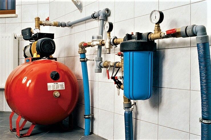
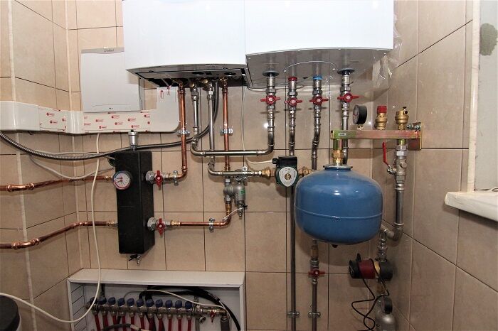
Only with stable water pressure heating equipment fulfills its service life and does not require frequent repairs. It has been noticed that if there is a reducer in the boiler piping that stabilizes the water pressure, the equipment works longer, and its spare parts do not wear out so quickly.

The main function of a water pressure reducer is to regulate the water pressure in the pipeline, protect against water hammer and other troubles associated with a sharp increase or surges in pressure. Most often, the reducer is installed between the water supply valve to an autonomous or internal system and the point of consumption.
The operation of the pressure reducing valve is automatic adjustment, that is, for full operation there is no need to connect additional equipment or mechanisms. In the event of an increase in water pressure, the device independently reduces the indicators, due to which the water supply to boilers, boilers and taps is normalized.
Description of the work process:
- well water or a centralized system moves with a certain stable pressure;
- due to technical or other reasons, a pressure surge occurs, and there is a risk of failure of equipment connected to the water supply system;
- water under increased pressure enters the gearbox and acts on a spring or membrane;
- the valve cross-section automatically decreases, followed by a decrease in pressure;
- The liquid reaches the water collection points under pressure not exceeding the established standards.
The pressure surge that occurs in the water supply system is called hydraulic hammer.
It can happen in a multi-storey building or in a cottage, and the result of a sudden increase in standard parameters is expensive equipment or pipeline elements that fail.

Thus, the WFD is the main tool for preventing undesirable consequences from water hammer, which you can independently install in your home water supply system.
The regulatory framework can be found in the documentation - GOSTR 55023, GOST 12678, methodological literature of the Scientific Research Institute of Plumbing.
Types and design features
Household regulators should be distinguished from industrial and commercial ones, and not only by size. For domestic ones, the productivity is much lower - on average 3 m³/h, while for industrial valve-reducers to reduce water pressure it reaches 15 m³/h and higher.
Household appliances are usually connected to the water supply system using a coupling method, and more productive ones are installed on main lines using flanges.
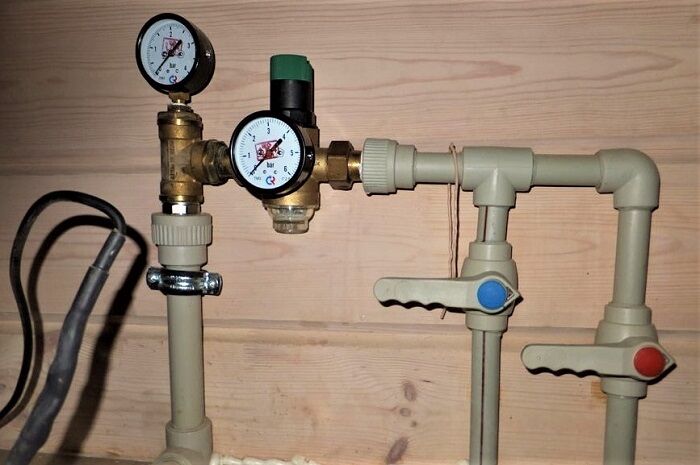
Almost all gearboxes are made from metals, more often from brass or brass alloys. The body is made in the form of a cross, the side pipes are intended for threaded connection to the pipeline, the top and bottom are for additional devices, for example, a pressure gauge.
There are two types of gearboxes that differ in design:
- piston;
- membrane
They are named after the main operating element located inside the body.
Piston gearboxes. The working part of the first category is a piston or piston assembly, which closes the valve under the influence of a spring.

When water begins to flow under increased pressure, the spring presses on the piston, which reduces the flow area. Thus, the liquid in the inlet chamber is under greater pressure than in the outlet chamber. Consequently, the pressure in the wiring located after the gearbox will remain normal.
Piston pressure regulators are used for water supply and heating systems if the temperature of hot water and coolant does not exceed the upper limit established by the manufacturer.
Diaphragm reducers are considered more powerful, durable, wear-resistant, and less sensitive to poor quality fluid in pipes. However, their cost is higher than their piston counterparts.

The operating principle of a diaphragm reducer is similar to that described above. Water enters the inlet chamber under high pressure and presses on the rod. Under the tension created by the spring and the rod, a gap is formed through which water enters the outlet with less pressure.
Membrane models, characterized by greater throughput and strength, are capable of reducing pressure from 25 bar or more to 6-7 bar or even lower.
If the inlet pressure is within normal limits, the liquid moves freely through the reducer without changing its parameters.
Installation and adjustment rules
If you have the skills to work with pipes, then you can install the RDV yourself. Beginners should not experiment; it is better to invite a plumber for responsible work.
Installation is carried out in the following order:
- We purchase a couple of products - for cold and hot water, preferably the membrane type. We also prepare tools and consumables for sealing - fum tape or tow, lubricant. You will need keys and a thread cutting tool.
- We turn off the water in the risers, notifying the neighbors in advance.
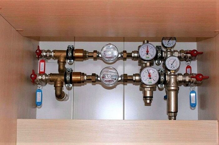
- We install an inlet valve on the pipe after the meter before the shut-off valve. We use the threaded method.
- First we fix the coarse filter, then the gearbox.
- We seal the joints.
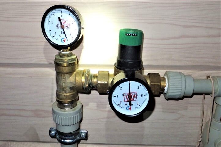
- If necessary, install a pressure gauge. We position it so that the dial is clearly visible.
- We connect the regulator to ball valve, seal.
After installation, we connect the water, turn off the ball valves and test the equipment.

The sequence of installing the regulator in the house is the same as for apartment installation.
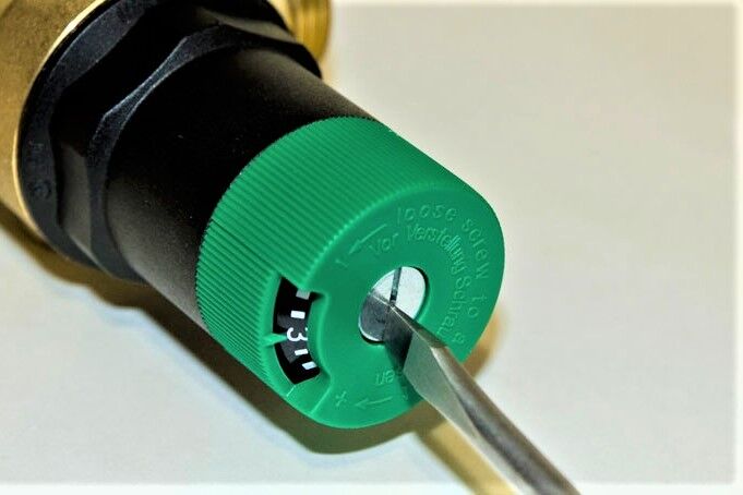
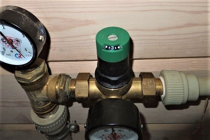
Most pressure regulators are manufactured and sold with factory settings. The normal pressure is considered to be 3 bar. If you need to reduce or increase the specified parameters, you can make the adjustment yourself.

An example of do-it-yourself adjustment. Initially, the pressure on the gearbox with pressure gauge is set at 6 bar; it must be changed to 3 bar.
As a result, the pressure at the inlet and outlet should become different. At the inlet, as initially - 4.5 bar, at the outlet after adjustment - 3 bar.
This method is simple and can be done right on the spot. It is not necessary to remove the device from the pipe. Adjustment on the table is made when a new device is installed in place of an old device or when the gearbox is mounted for the first time.
It is more difficult to maintain a device without a pressure gauge, since it is impossible to control the indicators. Usually they twist it at random, guided by the result. But we still recommend using a pressure gauge temporarily by inserting it instead of the plug.
Conclusions and useful video on the topic
A professional look at pressure reducers:
Helpful theory:
Hints on adjustment may also be contained in the operating instructions for the device. If it is not there (which is possible when ordering a gearbox in China), you can guess how to change the parameters by carefully studying the design of the device.
In case of difficulties, we recommend contacting professional plumbers who know exactly how to quickly and correctly adjust the water pressure in the apartment. You can also consult with them on choosing a suitable regulator.
Share with readers your experience of using a pressure reducer for a water supply system. Tell us what you based your choice of device on and whether you are satisfied with the purchase. Please leave comments on the article, ask questions and participate in discussions. The contact form is located below.


When I installed a water pressure reducer in the water supply system of my private home, I was faced with the dilemma of choosing the type of reducer.I opted for the membrane type, as advised in the material above, and was convinced of its reliability! Since the installation of the hot and cold water reducers, they have been working properly and have not had to be replaced. I would like to add that when assembling the gearbox, you need to pay special attention to sealing. For maximum reliability, I would recommend using not only fum tape, but also a special sealing lubricant. It should be used in addition to the fum tape, coating with such a lubricant layer by layer. With this method of sealing, the knees assembled with the gearbox will not leak, and everything will be under control!
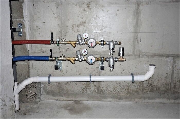
A pressure reducer is no less important element of an autonomous water supply than a hydraulic accumulator or well pump. All our equipment is located in an underground concrete caisson. After rummaging around on the Internet, I settled on a membrane-type gearbox. He's reliable. It has only been working for 3 years, but there have been no failures. In addition, there is the possibility of adjustment, which I took advantage of a year ago.
Hello, please tell me, I can’t understand - there is a drying pipe in the bathtub, but for some reason it doesn’t heat me up. It is water-based, supplied through hot water. Tell me how to install the valve correctly so that the water flows?
Hello, Victoria. It would be nice if you attached at least a rough diagram of how your wiring is arranged. This would make it much easier to understand what the problem is in order to give specific advice.
And so you will have to go through the main reasons that could lead to the fact that your heated towel rail does not heat:
1. It’s commonplace to drain the water; an air lock may have formed;
2.There may be a blockage; it is necessary to clean the inside of the heated towel rail pipe;
3. The pressure in the system has dropped;
4. The hot water supply valve is closed.
The last point is the simplest, I will attach several photos of diagrams so that you can understand where you need to check the position of the valves. If this does not help, then you will have to call a specialist.
Hello! A reducer with a pressure gauge installed at the inlet, where the pressure shows whether it is before it or already adjusted after it?
Does tightening the adjusting nut decrease or increase the pressure in the system downstream of the regulator?
it’s unclear... a little... how a pressure regulator can affect the water temperature!!!!! these are completely different categories... after all, hot water in the water supply system can be different (in temperature) depending on the time of year.... and the same with cold...((
and in general, as they say, learn the materiel......
It can easily and simply influence the temperature. You have adjusted the temperature, the pressure of hot or cold water has changed, therefore less of some water flows, there is a difference in the mixture, therefore a difference in the final temperature (it has become colder or hotter). Learn materiel
and everything else is correct.
And I had a two-pipe in the apartment, so the 3/4 supply pipe ran along all the walls in a circle, from it there were 1/2 bends at the top of the battery, then the pipe passed the last battery behind it, it turned around and as a return line it went along the supply to the boiler with connection 1/ 2 to the opposite lower corner of the battery and further into the boiler. All batteries work equally hot