Expansion tank for water supply: selection, design, installation and connection
An autonomous water supply system, which independently supplies water to distribution points as in a city apartment, has long ceased to be a curiosity.This is the norm of country life, which just needs to be properly designed, assembled and equipped with equipment capable of starting and stopping the system as the taps are used.
Stable operation of an independent network will be ensured by an expansion tank for water supply. It will protect against water hammer, significantly extend the service life of pumping equipment, guarantee regular filling of the system with water, and eliminate the need to carry it in buckets.
We are pleased to introduce you to the features of the device and the operating principle of the hydraulic accumulator. We carefully describe the rules for choosing a membrane tank, the specifics of installation and connection. We have supplemented the information offered for consideration with useful illustrations, diagrams and video tutorials.
The content of the article:
Characteristics of closed expansion tanks
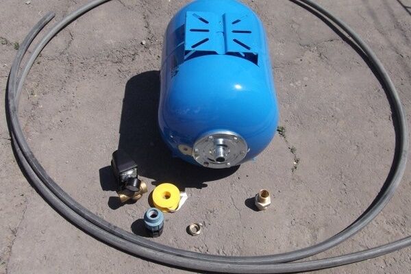
Hydraulic tank (or hydraulic accumulator, expansion tank) is a metal sealed container that serves to maintain stable pressure in the water supply and create water reserves of varying volumes.
At first glance, choosing and installing this device should not cause difficulties - in any online store you can see many models that only differ slightly in shape and volume, but do not differ significantly in their functionality.
It's not like that at all. There are many nuances in the design of the expansion tank and the principle of its operation.
Features of the device and design
Different models of expansion tanks may have restrictions on the method of use - some are designed only for working with process water, others can be used for drinking water.
By design, hydraulic accumulators are divided into:
- tanks with replaceable bulb;
- containers with a fixed membrane;
- hydraulic tanks without membrane.
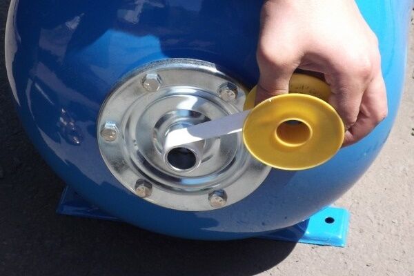
On one side of the tank with a removable membrane (for a tank with a bottom connection - at the bottom) there is a special threaded flange to which the bulb is attached. On the reverse side there is a nipple for pumping or bleeding air or gas. It is designed to be connected to a regular car pump.
In a tank with a replaceable bulb, water is pumped into the membrane without coming into contact with the metal surface. The membrane is replaced by unscrewing the flange held in place by the bolts. In large containers, to stabilize the filling, the rear wall of the membrane is additionally attached to the nipple.

The internal space of the tank with a fixed membrane is divided into two compartments. One contains gas (air), the other contains water. The inner surface of such a tank is covered with moisture-resistant paint.

There are also hydraulic tanks without a membrane. The compartments for water and air are not separated in any way. The principle of their operation is also based on the mutual pressure of water and air, but with such open interaction, mixing of the two substances occurs.
The advantage of such devices is the absence of a membrane or bulb, which is the weak link in conventional hydraulic accumulators.

The diffusion of water and air makes it necessary to service the tanks quite often. About once a season you have to pump in air, which gradually mixes with water. A significant decrease in air volume, even at normal pressure in the tank, causes the pump to turn on frequently.

Operating principle of a hydraulic accumulator
Closed hydraulic tanks for water supply They work according to the following scheme: the pump supplies water to the bulb, gradually filling it, the membrane increases and the air that is located between the bulb and the metal body is compressed.
The more water enters the pear, the more it puts pressure on the air, which, in turn, tends to push it out of the container. As a result, the pressure in the tank increases, which causes the pump to turn off.
For some time, when water flows through the system, compressed air maintains the pressure. It pushes water into the water supply.When its amount in the membrane decreases so much that the pressure drops to the lower limit, the relay is activated, turning the pump on again.

Classification by area of application
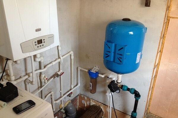
Tanks for water supply and for the heating system should not be confused, so when choosing, you need to find out their purpose. For clear identification, manufacturers paint hydraulic accumulators for heating red and for water supply blue.
However, some do not adhere to such markings, so the following data can serve as a distinctive feature of devices:
- for water supply, the maximum temperature of use of the hydraulic accumulator will be up to 70 °C, the permissible pressure can reach 10 bar;
- devices intended for heating systems can withstand temperatures up to +120 °C; the operating pressure of the expansion tank is often no higher than 1.5 bar.
All the most important parameters are indicated on the decorative cap (nameplate) that covers the nipple.

The list of functions that a hydraulic tank performs in a cold water supply system is much broader:
- Maintaining an even and constant pressure in the water supply. Thanks to the air pressure, the pressure is maintained for some time even when the pump is turned off, until it drops to the set minimum and the pump starts working again.Thus, the pressure in the system is maintained even when several plumbing fixtures are used simultaneously.
- Protection against wear of pumping equipment. The water reserves contained in the tank allow you to use the water supply for some time without turning on the pump. This reduces the number of pump operations per unit of time and prolongs its operation.
- Protection against water hammer. A sharp jump in pressure in the water supply when the pump is turned on can reach 10 atmospheres or more, which negatively affects all elements of the system. The membrane tank takes the shock, equalizing the pressure.
- Creation of water reserves. When there is a power outage, the water supply system will continue to supply water for some time, even if only for a short time.
For piping the water heater, expansion tanks are used that can withstand high temperatures.
Materials for hydropneumatic equipment
The expansion tank membrane is made of different materials that can withstand different temperature ranges during operation.
The following are used in hydraulic accumulators:
- Natural rubber - NATURAL. The material can come into contact with drinking water and is used to accumulate cold water. Over time, it may begin to leak water. Withstands temperatures from -10 to 50 °C above zero.
- Synthetic butyl rubber - BUTYL. The most universal, waterproof, used for water supply stations, suitable for drinking water. Operating temperature can range from -10 to 100 °C.
- Synthetic rubber made from ethylene propylene - EPDM. More permeable than the previous one, it can come into contact with drinking water. The permissible temperature range is from -10 to 100 °C.
- SBR rubber is used only for process water. The operating temperature is the same as previous brands.
To organize cold water supply, it is necessary to choose tanks with a bulb made of food-grade rubber with improved elastic properties, which will better absorb water hammer and maintain a stable water pressure in the system.
The tank body is most often made of alloy steel, resistant to corrosion, coated on the outside with paint and varnish. You can also find stainless steel containers on sale, which are very durable, but also expensive.
Calculation of tank volume before choosing
Tanks with capacities from 24 to 1000 liters are available for sale. Which one to choose will be determined by calculations, the result of which should be rounded up. When choosing a tank with a removable membrane, you should remember that the volume of water occupies 30% of the total volume of the tank, that is, in a 100-liter tank the water supply will be approximately 30 liters.

The peculiarity of small tanks is that they often do not have a valve to bleed air from the rubber bulb. This may create inconvenience during operation. Large containers have such a valve, and in addition to creating a larger supply of water, they are better able to maintain stable pressure in the system.
Calculation of the total volume of a hydraulic tank for a closed type water supply is calculated using the following formula:
Vt=K*Amax*((1+Pmax)*(1+Pmin))/(Pmax-Pmin)*(1+Pair),
Where:
- Vt is the total volume of the hydraulic tank;
- Amax – maximum possible water consumption per minute, liter;
- K – coefficient (see table), depending on the pump power;
- Pmax – relay settings when equipment is turned off, bar;
- Pmin – relay settings when starting equipment, bar;
- Pair. – pressure in the hydraulic tank (in its gas cavity), bar.
The K coefficient can be determined from the following table:

Some manufacturers also calculate the volume of the hydraulic tank differently:

Horizontal and vertical orientation
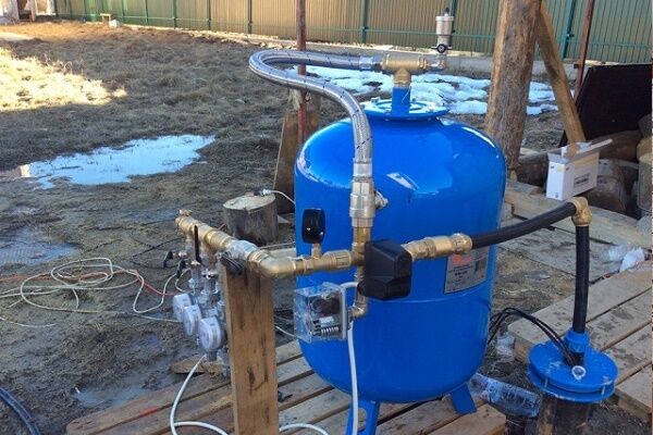
The choice between a vertical and horizontal tank depends on the characteristics of the room. If the room is small or the volume of the container is impressive, then in order not to take up much space, install a vertical container.
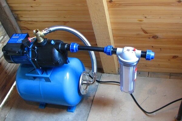
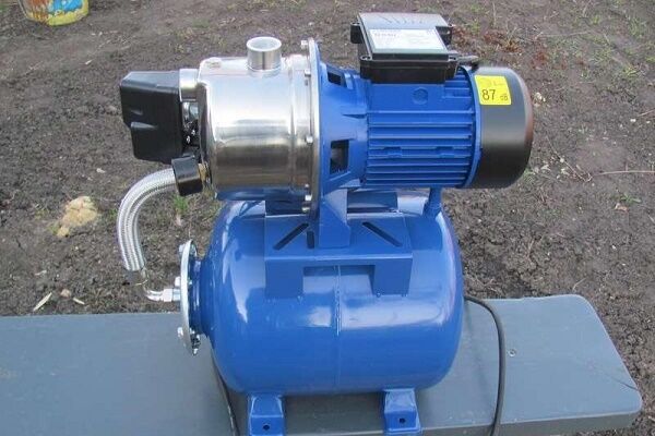
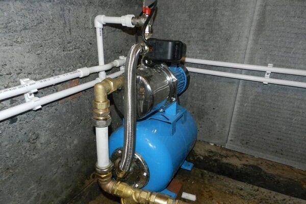
The horizontal tank has a smaller capacity, can be hung on the wall, and also serve as a support for installing a surface pump. Special fastenings are provided for its installation. Large tanks are produced only in a vertical design and are installed on legs.
Summarizing all of the above, it can be noted that the choice of a hydraulic accumulator must be made between the following distinctive properties:
- operating pressure;
- manufacturer country;
- larger or smaller volume;
- replaceable or not rubber membrane;
- membrane for industrial or drinking water;
- Case material: stainless or enameled steel.
To avoid difficulties with replacing components in the future, it is better to choose the most popular device models. Rubber bulbs for them are always available for free sale; if you need an urgent replacement, you won’t have to wait long for delivery.
Connection diagrams for hydraulic tanks
For hot water system installation of an expansion tank carried out on the section of the circulation line, the suction line of the pump, closer to the water heater.
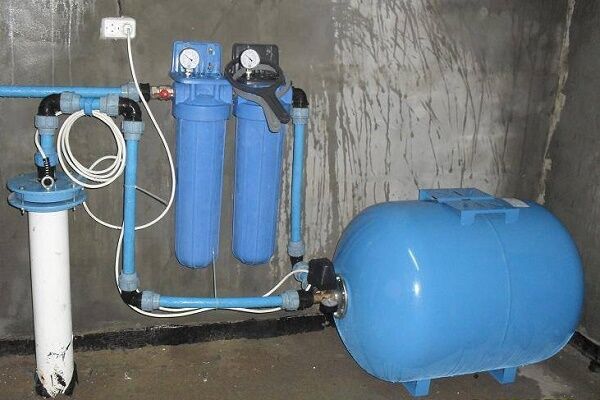
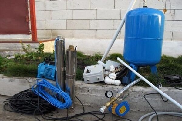
The tank is equipped with:
- pressure gauge, safety valve, air vent - safety group;
- shut-off valve with a device that prevents accidental shut-off.
In a water supply system where water heating equipment is present, the device takes on the functions of an expansion tank.

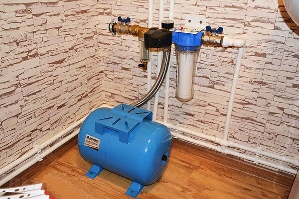
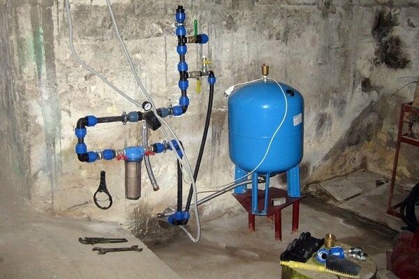
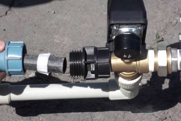
In the HV system, the main rule when installation of a hydraulic accumulator — installation at the beginning of the piping, closer to the pump.
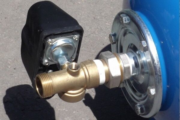
The connection diagram must include:
- check valve and shut-off valve;
- security group.
Connection schemes can be very different. The connected hydraulic tank normalizes the operation of the equipment, reducing the number of pump starts per unit of time and thereby extending its service life.

In a scheme with a boost pumping station one of the pumps runs constantly. This system is installed for houses or buildings with high water consumption. The hydraulic tank here serves to neutralize pressure surges, and to accumulate water, a container of as large a volume as possible is installed.
Installing an expansion tank
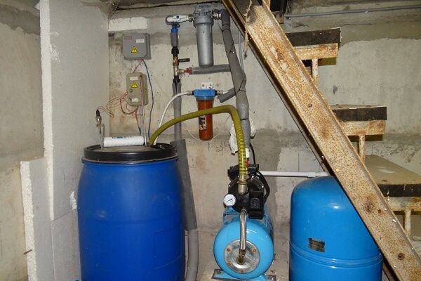
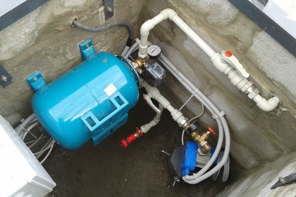
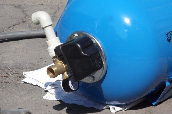
Before starting work, check the hydraulic accumulator for damage.The device is installed in a soundproofed room at above-zero temperatures. In order to have access to the drain tap, shut-off valves, etc., the distance from the tank to the ceiling and walls is left at least 0.6 m.
It is also necessary to provide the possibility of filling the tank and draining the water in the room. The fasteners and installation location must be able to withstand 100% filling of the container.

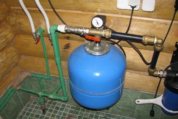
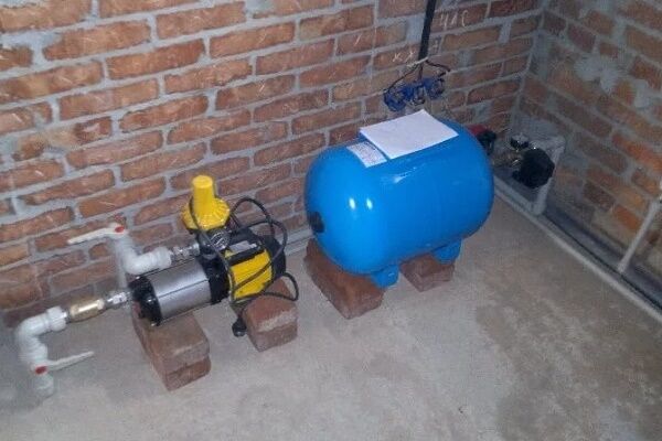
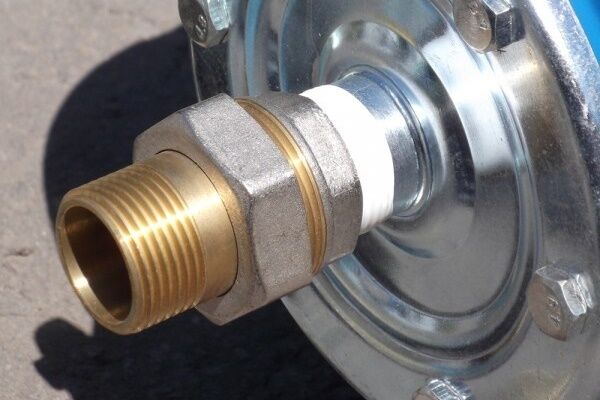
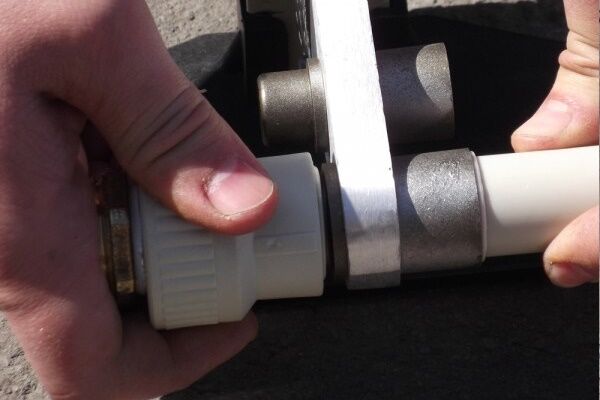
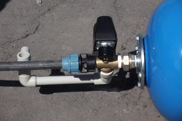
The hydraulic accumulator should not be subjected to mechanical and static loads; it is undesirable to allow pipes and assemblies to impact it. The tank is screwed to the floor using rubber gaskets. A check valve and a drain valve are installed at the entrance to the hydraulic tank.
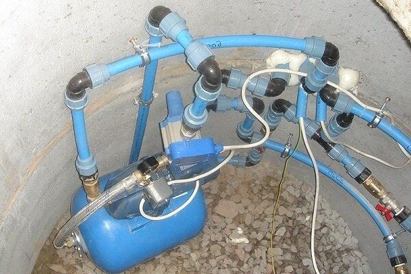
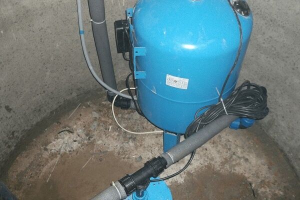
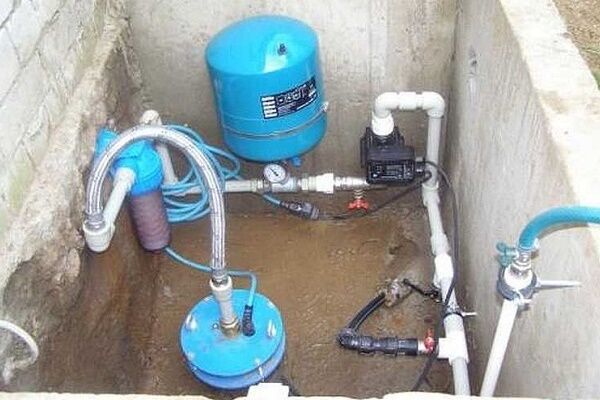
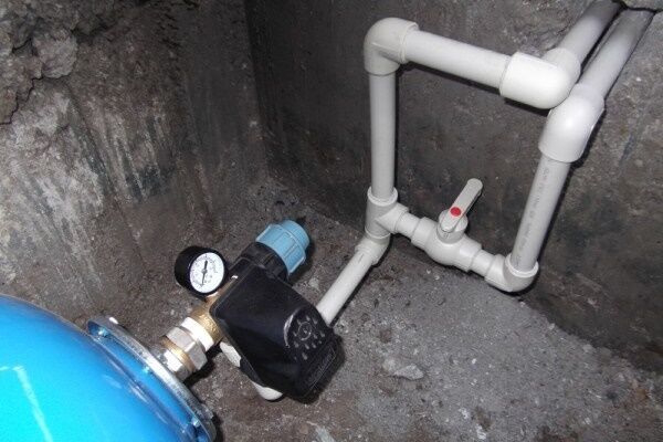
The listed steps were required to install the hydraulic accumulator piping, which was carried out on the daytime surface. For further action you need to move to the caisson.
After the final assembly of the system, all that remains is to carry out control tests and start the water supply circuit.
Features of adjusting the hydraulic accumulator
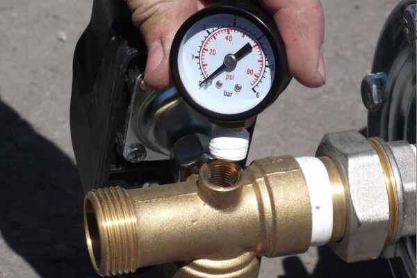
Expansion tanks for water supply are sold with standard manufacturer settings - often the pressure in the air compartment is already set at 1.5 bar.The permissible pressure is always indicated on the label and the manufacturer does not recommend deviating from the specified parameters, especially in the direction of increasing it.
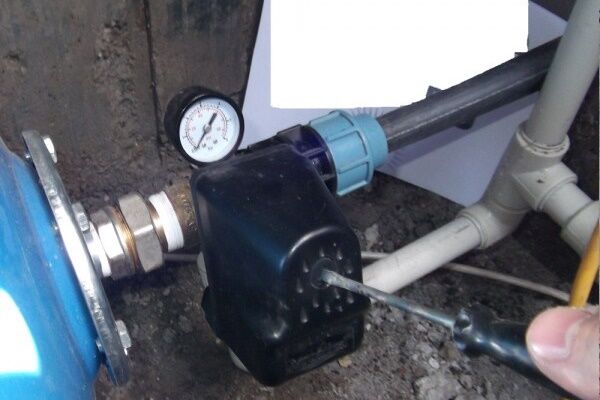
Before proceeding with the adjustment, the system is disconnected from the power supply and the shut-off valves are closed. The membrane tank is completely emptied by draining the water - an accurate pressure indicator can only be measured when the water compartment is empty.
Next, pressure readings are taken using an accurate pressure gauge. To do this, remove the decorative cap from the spool and bring the device. If the pressure differs from the required one, it is brought into compliance by pumping or bleeding excess air.

When adjusting the pressure in the gas compartment of the tank, the manufacturer fills it with an inert gas, for example, dry nitrogen. This prevents corrosion of the inner surface. Therefore, users are also recommended to use technical nitrogen to increase pressure.
Setting the tank pressure in the water supply system
The pressure in a closed tank is always set slightly lower (by 10%) than the pressure level when starting the pump. By adjusting the pressure in the device, you can adjust the water pressure. The lower the gas pressure in the hydraulic tank (but not less than 1 bar), the more water it will hold.
In this case, the pressure will become uneven - strong when the tank is full and increasingly weak when it is empty. To ensure a strong and even flow of water, set the pressure in the chamber with air or gas to within 1.5 bar.

Adjusting the hydraulic tank in the water heater trim
The expansion tank, which is used for hot water supply, should initially not contain water. The pressure in the device is set at a value that is 0.2 greater than the upper pump shutdown threshold.
For example, if the relay is configured to turn off the equipment at a pressure of 4 bar, then the pressure in the gas compartment of the expansion tank should be set to 4.2 bar.
Installed in the water heater piping, the tank does not serve to maintain pressure. It is designed to compensate for expansion when water is heated. If you set the pressure in it to a lower value, then there will always be water in the tank.
Hydraulic tank maintenance rules
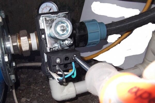
A routine inspection of the expansion tank consists of checking the pressure in the gas compartment. It is also necessary to inspect the valves, shut-off valves, air vent, check the operation of the pressure gauge and water pressure switch. To ensure the integrity of the tank, an external inspection is carried out.

Despite the simplicity of the device, expansion tanks for water supply still do not last forever and can break. Typical causes are rupture of the membrane or loss of air through the nipple. Signs of breakdowns can be determined by the frequent operation of the pump and the appearance of noise in the water supply system. Understanding how your accumulator works is the first step to proper maintenance and troubleshooting.
Installation of an open type hydraulic tank
An open-type device is used less and less often, as it requires constant user intervention in its operation. An open expansion tank is an unsealed container that serves to form pressure in the water supply, water storage, and also serves as an expansion chamber.

The tank is installed above the highest plumbing point, for example, in the attic, water enters the system by gravity. Every meter the device rises increases the pressure in the water supply by 0.1 atmospheres.
To automate the process of providing water, the tank is equipped with a float switch and an automatic relay is installed that will turn the pump on and off.

This method of organizing water supply requires regular monitoring by the user, otherwise the water may freeze at subzero temperatures (if the room is not heated). The liquid will evaporate, so you will have to constantly add it.
In addition, such a container is bulky and not aesthetically pleasing; it requires an attic space in the house. But the main drawback of the device is that the tank is not designed to work under conditions of high water pressure in the system.
Conclusions and useful video on the topic
Video #1. All about expansion tanks - classification, purpose, adjustment and signs of problems:
Video #2. Incorrect operation of the pumping station is often associated with malfunctions of the hydraulic accumulator:
Video #3. Nuances of choosing hydraulic tanks for water supply:
Even at the stage of planning and developing a water supply system, it is necessary to think through all the fundamentally important points and calculate all the parameters. If you are not confident in the infallibility of your calculations and the correct choice of a hydraulic tank for water supply, it is better to contact specialists.
Most companies that sell professional equipment provide consultations or even carry out calculations for free. This will help avoid mistakes and unnecessary expenses.
We are waiting for your comments with stories about your own experience in using an expansion tank, with questions that arose during your review of the information provided. We are interested in your comments and possible suggestions. You can comment on the material in the block below.


The information is presented in an accessible manner, with all the subtleties and features. I didn’t think that tanks for water supply and for heating systems were so different. I didn’t realize that they needed to be used strictly for their intended purpose, without confusing one with the other. They chewed everything up, even using formula calculations. I thought that installing the tank would be a piece of cake, but it would be better to contact a plumber.
The article states: “For a hot water supply system, the installation of an expansion tank is carried out in the section of the circulation line, the suction line of the pump, closer to the water heater,” and in the diagram below the tank is connected to the cold water line. Is this not a connection or am I missing something? Can you explain?
When they installed the hot water system for me, the installers told me that there are also membraneless accumulators.They are cheaper and, in their opinion, better, since there is no such element as a separating membrane. But I think that if suddenly water is lost from the hydraulic accumulator, then all the damping gas will also leave. Am I understanding correctly? Please explain why membraneless accumulators are better then?
Hello. They have different operating principles:
1. The principle of operation of a station with a hydraulic accumulator. Water through a supply hose, most often equipped with a coarse filter and a check valve that prevents the outflow of water, flows from the source to the hydraulic accumulator. When the membrane is filled, in combination with the air pressure in the tank, a signal is sent to the pressure switch, and accordingly the pump turns off. When, as a result of the operation of the water supply station, the pressure drops to a certain point, the relay receives a signal and turns on the pump again.
2. The principle of operation without a hydraulic accumulator is even simpler. The tap opens, the pump automatically turns on and starts pumping water. The tap closes and the pump turns off.
For water supply systems where there are few water users - 1-2 people, option 2 is quite suitable, because such stations are more compact and the water in the pear does not stagnate. However, there is also no reserve of water that remains in the accumulator during a power outage, and if a family of a large number of people uses it, that is, water is consumed in a larger volume, the pump fails faster due to more intense work activity.
Please tell me what to do if, when you turn on the water, the tank starts clicking and the arrow on the regulator jumps. The water comes in fits and starts.