Slope of the drainage pipe: calculations, standards and features of installing drainage on a slope
An impeccably designed and well-calculated drainage will collect and drain groundwater from the site.It will protect the foundation from premature destruction and ensure normal growth of cultivated plants. In order to ensure spontaneous drainage of the water collected by the system, it is necessary to ensure the slope of the drainage pipe. And its device requires accurate information, right?
You will learn everything about the angle at which drainage pipes are laid and how to properly organize a drainage system from our article. By following the technical recommendations we provide, you will be able to design and accurately calculate your drainage network. The basis for the given data is building regulations.
To help independent craftsmen, the technology of constructing a water drainage system is described in detail, and the specifics of the calculation and installation of its components are thoroughly analyzed. Photos and videos are attached for visual perception of the information.
The content of the article:
Design features of drainage
There are three types of drainage systems, each of which has its own design features: horizontal, vertical, combined.
The working elements of horizontal drainage can be:
- tubular drains;
- gallery drains;
- trays and trenches.
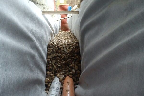
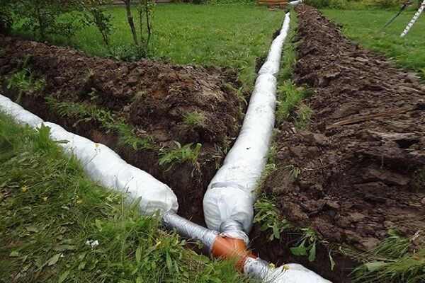
A system of drainage pipes in combination with a filter coating (multilayer) is a tubular drain.
Multi-layer filter coating, in this case, is done to prevent washed-out soils from entering the system. According to standards, the drainage circuit is always equipped inspection wells.

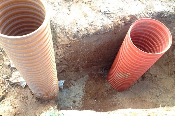
Unlike tubular drains, gallery drains are made from pipes of a larger cross-section. There are holes on the walls of the pipes for collecting waste.
The process of installing gallery drains also involves filling with additional filtration with geotextiles.

A drainage system with trays and trenches is usually made in conditions where the groundwater level is allowed to reach 1.3-1.5 m. On stable soils, trenches are made with slopes; on unstable soils, the trenches are reinforced with reinforced concrete structures.
A vertical drainage system consists of a set of wells (wells) connected by a collector. Sewage is removed through the collector line using a pumping station. Also, drainage of wastewater on vertical drainage can be carried out by discharging into the lower layers of the soil.
The combined drainage system combines horizontal and vertical schemes.It is characterized by specialists as a complex drainage scheme and is usually installed in areas where highly efficient soil drainage is required.
Surface and deep schemes
Based on the calculated parameters of drainage depth, surface and deep drainage schemes are distinguished. The purpose of the surface scheme is to collect and drain atmospheric precipitation products, as well as nearby groundwater.
The purpose of the deep scheme is to lower the groundwater level, collect it and drain it beyond the boundaries of the site where the construction site is located.

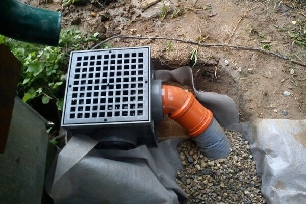
The scheme of water inlets for storm sewer systems supports point or linear design. In the first case, wastewater is removed from local sources (drains, sidewalk pits, entrance collections).
The linear scheme ensures water drainage throughout the entire facility. As a rule, a combined solution with the implementation of both schemes is used on residential construction sites.
Deep drainage is required in almost all cases of private housing construction and landscaping of commercial plots. This is an effective protection of those elements of building structures that are located below the zero level (foundation, basements, plant root systems).
It is permissible to exclude the construction of deep drainage at elevations where the groundwater level does not exceed 1.5 m, where effective soil drainage is observed.

Designing a deep drainage scheme requires high precision calculations. Even a minor error in calculations can cause low system efficiency.
The practice of installing such schemes often indicates a common mistake - inaccurate calculation of the depth of drains. The result is uneven drainage of water from the territory of the facility or, even worse, flooding of fertile lands and basements.
There are other articles on our website where we examined in detail the construction of various drainage options. We recommend that you familiarize yourself with them:
- Installing drainage around the house: designing and installing a do-it-yourself drainage system
- How to make foundation drainage for a house with your own hands: secrets of proper organization
- How to properly drain a garden plot with your own hands: we analyze the correct technology for arrangement
Calculations and standards for drainage construction
The calculated values that will be required for the construction of a drainage system are usually:
- pipeline diameter size;
- pipeline laying level;
- pipe slope values;
- density of the geotextile filter.
And more details about each point.
Value #1 - design diameter of pipelines
The required diameter of pipelines is calculated with an emphasis on the design parameters of drainage intensity.
For private housing construction, pipes with a diameter of 100 mm are usually optimal. Their standard capacity is about 7 l/s, which is fully consistent with design standards in most cases.
Meanwhile, increasing the diameter of the drain allows you to cover a larger working area and increase the efficiency of the system.
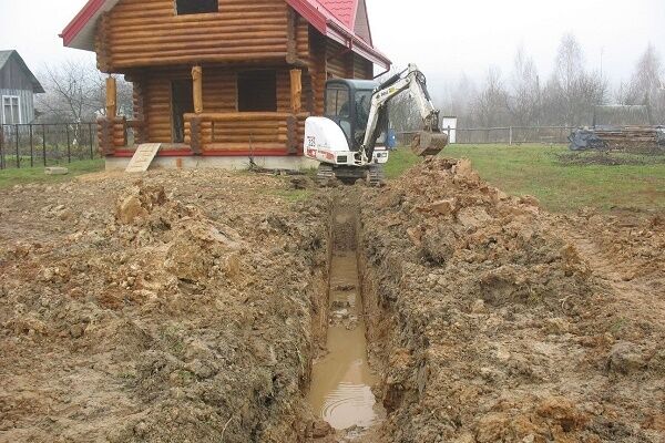
Value #2 - system depth
The laying level of drainage pipelines, according to existing standards, is determined taking into account two criteria:
- Soil freezing level.
- Foundation depth.
The degree of soil freezing is directly related to the climatic properties of the area. Therefore, for each individual territory this parameter may differ.
But in any case, the calculation of the depth of laying drainage pipes is carried out from the end point of soil freezing with the addition of at least 300-500 mm of additional depth to this value.

The same algorithm is used to calculate foundation drainage, but from the end point of the foundation.
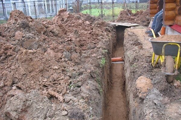
Value #3 - slope of drainage pipes
SNiP standards clearly indicate at what slope the drainage system pipes should be installed. According to these standards, the minimum values of the drain slope must be taken taking into account the permissible minimum flow rate of wastewater.
At the same time, it is additionally stipulated that for pipes with a diameter of 150 mm, the minimum permissible slope must be at least 8 mm per meter of length, and for pipes with a diameter of 200 mm - at least 7 mm per meter of length. In certain sections of networks, it is allowed to reduce these parameters to 7 mm and 5 mm, respectively.
The permissible maximum slope of drainage pipes per meter of length is 150 mm. A slope greater than this value is permissible only on branches from plumbing fixtures with a branch length of up to 1.5 m.
In undesigned drainage sections where pipes with a diameter of 40-50 mm are used, a slope of up to 30 mm per meter of length is acceptable. And for pipes with a diameter of 85-100 mm and under the same conditions, the slope level is allowed to be no more than 20 mm per meter of length.

If trays are used as drainage elements, the slope level is taken with an eye to the rate of wastewater that ensures the effect of self-purification of the liquid. Acceptable filling of trays is no higher than 80% with a tray width of at least 20 mm.
The width of the trays is calculated based on the results of hydraulic calculations and depends on the design features of the elements. However, if the height of the tray is more than 50 mm, the width cannot be less than 70 mm.
Value #4 - required geotextile density
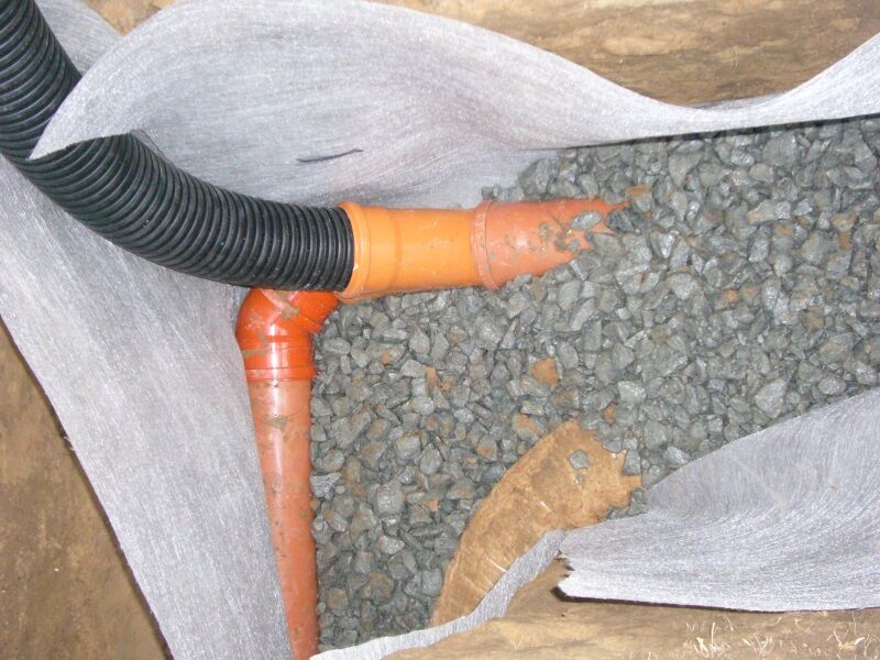
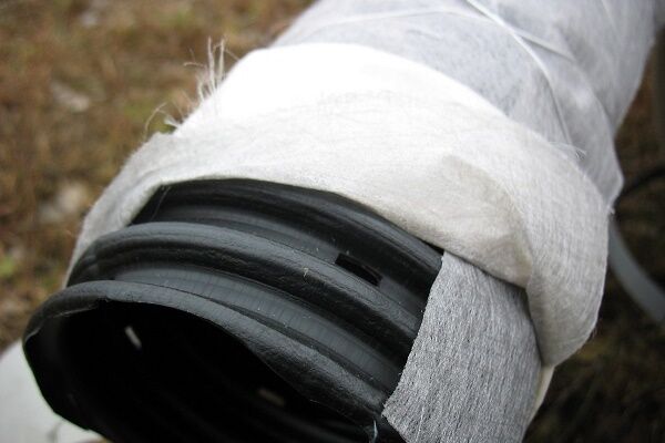
When the drainage system design involves the use of perforated corrugated pipes as drainage, it is recommended to use a geotextile filter shell (geotextile) along with the coating of such pipes.
The geotextile fabric acts as a filter element and prevents clogging of the pipeline with small soil particles. To obtain the maximum filtration effect, it is necessary to calculate the density of the geotextile filter. The optimal calculated value for household drainage systems is considered to be a density of 100-150 g/m2.
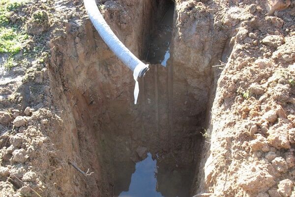
Features of installing drainage on a slope
Drainage systems provide drainage due to the slope of the drains. It would seem that if the site is located on a slope, water should be drained from the site naturally, and there is simply no need to install a drainage system.
However, in such cases the situation is completely different, and drainage of a site on a slope becomes just as important as for sites with a slope of less than 8%.

Of course, drainage of areas on slopes has its own characteristics. Often the soil on steep slopes has a heterogeneous structure. Different levels of groundwater may be observed at different horizons.
Therefore, it is often necessary to use combined types of drainage to ensure the required degree of drainage of the entire territory of the site.
Meanwhile, when constructing drainage systems on slopes with a level of more than 8%, the standards allow for the absence of drainage inspection wells.
Scheme and order of the system
The organization of drainage in an area with a slope level of more than 8% begins with geological surveys. Based on the survey results, aquifers and groundwater levels are determined. Based on the information received, a drainage project for the site on the slope is being developed, and construction work is being carried out.
Ultimately, the problem of eliminating the possibility of soil erosion by chaotic natural drainage due to the steepness of the slope must be solved.
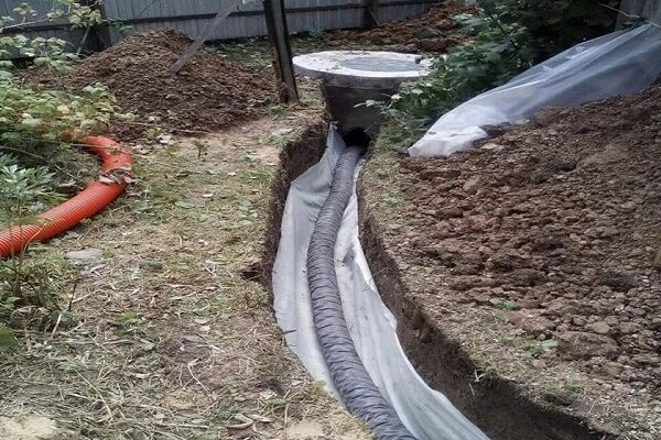
In a simple version, this is done approximately like this:
- The first horizontal surface drain is created at the top elevation of the site.
- A second horizontal surface drain is created at the lower elevation of the site.
- Both drains are connected by perpendicular trenches.
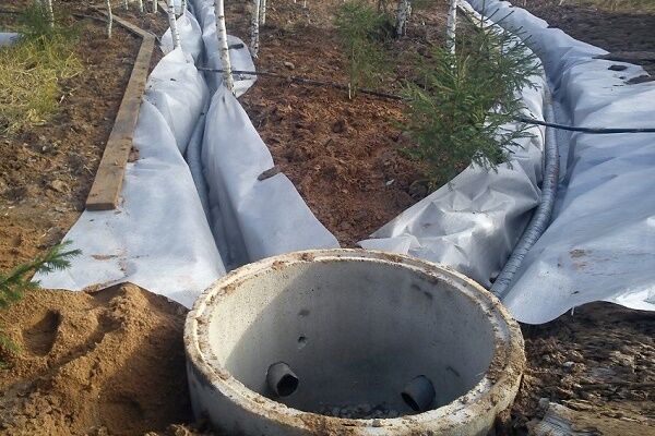
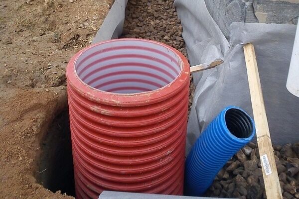
- From the horizontal drain of the lower level, a branch is made to drainage well.
If the landscape of the site has a stepped, complex shape and the project of the facility provides for the construction of retaining walls, stairs, transition platforms, for each of the project elements it is necessary to construct point drainage systems that turn into a system of linear drainage systems.
Large areas located on slopes, as a rule, are equipped not with single surface drains, but with full-fledged herringbone-type water collection and drainage systems.
A branched drain is installed on the upper horizon and is combined with a collector drainage circuit surrounding the construction site. From the circuit, wastewater is transported to a collection site outside the site or to storm sewer.

This design solution is called ring drainage. Thanks to the construction of a protective contour located around the perimeter of the facility, it is possible to bring the groundwater level under control. In turn, the “herringbone” ensures the collection of water from the surface of the site and its effective drainage.
Installation of ring drains is carried out at some distance from the construction site. This factor makes it possible to construct a ring drainage system directly at the stage of operation of utility structures.
It should be noted that the effectiveness of lowering the groundwater level within the internal part of the contour directly depends on the following parameters:
- pipe depth level;
- depth level of galleries;
- well depth level (if any).
The effectiveness of protection is also influenced by the dimensions of the circuit.
Conclusions and useful video on the topic
Several practical tips on laying drainage pipes will help you independently cope with the installation of drainage in a suburban area.
Protecting areas (territories) from moisture oversaturation is an urgent task that has to be solved in almost every construction case. Existing developments of drainage systems allow solving such problems.
The main point is to calculate and choose a drainage device option that would be ideal in each specific case.
Are you planning to arrange the drainage of the site yourself, but have encountered difficulties at the design stage? Ask your questions in the comments block - we will try to help you.
Or have you successfully built a drainage system and want to share your experience with other private homeowners? Write your recommendations, add photos under our article - many users will find your experience useful.


Good afternoon. I would like the information to be supplemented with a more detailed description of the pipes used for drainage. The choice is now huge: plastic, asbestos-cement, ceramic... And it’s quite difficult for the average person to choose, especially since each manufacturer advertises its own products. Therefore, it is advisable to familiarize yourself with at least a brief description of the material and recommendations for its use.
Good day, Andrey.
Asbestos-cement and ceramic have almost identical characteristics. Rarely used for several reasons:
1. Difficulty in installation. Due to the large weight, unloading on site is problematic. The material is quite fragile. Requires careful preparation of the base and backfilling.
2. Service life is 20-30 years.
3. The cost of the material itself, especially ceramics, is significantly more expensive than its analogues.
PVC pipes, if the drainage system technology is followed, do not have any disadvantages. They occupy leading positions in sales for the following reasons:
1. Easy to install. Unlike the two previous options, they are flexible and light in weight. They come in coils of 40-50 meters, which makes it easy to deliver and lay in a trench.
2. Different strengths. Double-layer ones are naturally tougher than single-layer ones. The stiffness class is indicated by the letters SN; the higher the number after, the stiffer the pipe. The maximum value is SN16.
3. Plastic is not subject to decomposition and destruction. Service life of at least 50 years.
4. Low cost of pipes.
Regarding application:
— two-layer ones are used in case of great depth;
— the diameter of the pipe is the absorption area. The higher the swampiness of the area, the larger the diameter required.