How to properly make grounding in a garage with your own hands - instructions for arrangement and operation
Grounding a garage is not difficult if you know the installation requirements and the features of electrical installations. It is necessary if this object is used not only as a vehicle storage room, but also as a workshop where repairs can be carried out. The repair process uses power tools, even stationary ones, which are powered by a current of 380 volts. And this is already dangerous for humans.
The content of the article:
Requirements for PUE
The Rules are a voluminous document consisting of main chapters. One of them, number 1.7, is called “Grounding and protective safety measures.” It states that there are several grounding schemes, one of which can be used in the garage. It all depends on the voltage that is used to power electrical equipment and tools.
This power supply indicator directly depends on the resistance of the ground loop. Because the higher the resistance, the slower the current flows through the conductor from which the garage ground is formed. And it should happen quickly.
In this case, human resistance should always be greater than grounding resistance. If a person touches an electrical installation where there is an electricity leak, the latter must pass through a conductor that has less resistance. And a person is a conductive object.
The relationship between voltage and resistance of the ground loop is given in the table.
| Voltage, V | Resistance, ohm |
| 127 | 20 |
| 220 | 10 |
| 380 | 5 |
Paragraph PUE 1.7123 states which conductors cannot be used as grounding:
- gas, water and heat pipes, sewerage and pipelines through which explosive and flammable substances move;
- water supply, if insulating inserts are inserted into its lines;
- cables, if cable wiring is organized;
- tubular wires;
- metal hose;
- lead braids of wires and cables.
What types of grounding exist
According to the rules for electrical installations, paragraph 1.7.3, there are 6 power supply circuits used in electrical networks. 4 types are acceptable for the garage:
- with a combination of the protective and neutral circuits, designated TN-C;
- with partial alignment – TN-C-S;
- with dedicated protective circuit and zero - TN-S;
- with solidly grounded neutral – TT.
When choosing one of the power schemes, you will need to select the scheme and ground loop in the garage.
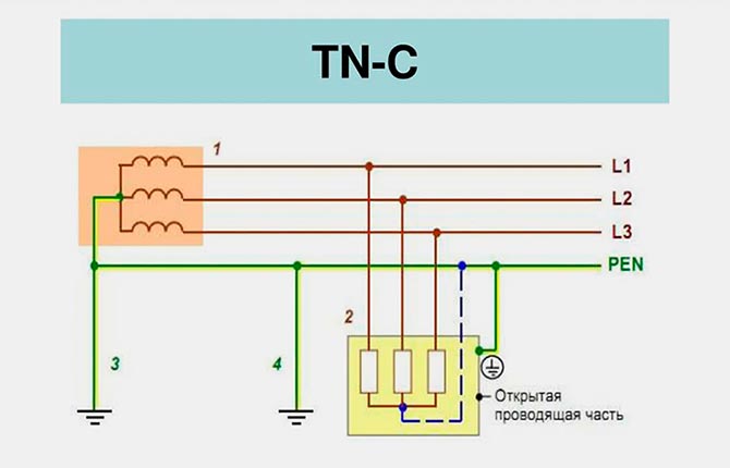
TN-C
The most common connection system. 4 wires are inserted into the input panel: three are phases, one is zero. This zero simultaneously serves as grounding. There is no separate grounding conductor, and this is a clear savings. But this scheme has several disadvantages. One of them is serious.
For example, somewhere in the area where the neutral wire was laid from the transformer to the garage, a break occurred. Three-phase power is supplied to the facility, but there is no grounding. It turns out that if you turn on an electrical device, potential will be applied to its body. And if a person touches the metal body with his hand, he will get an electric shock.
It’s easier with a single-phase connection, where the voltage is 220 volts. If the neutral, or grounding, conductor is broken, then the electrical installations cannot be turned on.No power means no risk of electrocution. In this regard, a three-phase connection is dangerous.
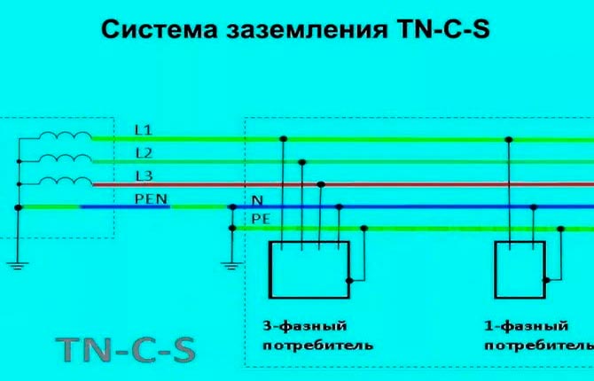
TN-C-S
A safer wiring option. Here, as in the previous case, 4 wires come out of the transformer substation: three phase, one neutral. But in the area up to the garage, the latter is divided into two. And the garage already includes 5 circuits:
- 3 phase;
- 1 zero;
- 1 grounding.
The grounding itself can be carried out either at the substation or at the disconnection site.
If single-phase power is supplied to the garage, then the neutral wire can also be divided into 2. Instead of a two-core wire, a cable with three wires will be connected to the electrical panel.
This garage connection diagram must have an RCD that is inserted into the neutral circuit. The reason is that there is a high probability that if the combined conductor is damaged, a potential may arise either from the transformer or from other garages connected to a single network.
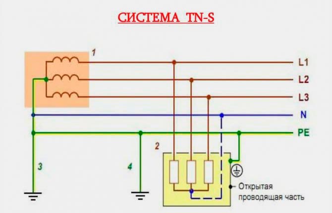
TN-S
The most reliable garage connection system. Here, 5 single-core cables or 1 five-core cable are led into the panel from the substation. Separate circuits are drawn for 3 phases, for zero and grounding. If the neutral wire suddenly breaks, the grounding will work independently. It is impossible to receive an electric shock in this circuit.
But this is the most expensive connection option, so it is rarely used in garages.
TT
The most common scheme, and not only in garages. If the power supply of electrical installations is three-phase, then a four-core cable is installed, 3 of which are phase, one is neutral. The latter must be grounded, hence the name of the power supply - with a solidly grounded neutral.
Grounding is created separately. To do this, a wire is drawn from each installation and connected to the ground loop.The latter is done with your own hands. For example, 3 steel pins up to 3 m long are driven into the ground and tied with metal tape.
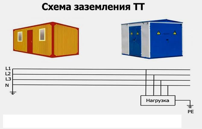
An individual grounding circuit is a reliable design if done correctly. It ensures 100% electrical safety of the garage.
Ground loop arrangement diagram
Before you make grounding in the garage with your own hands, you need to understand the structure of the system. And it consists of metal conductors. Some are located vertically, others horizontally. Vertical ones are called electrodes.
Vertical ground electrode
There are recommended and non-recommended materials for making vertical grounding elements in a garage. The first includes steel angles, pipes with a diameter of more than 32 mm and a wall thickness of more than 3.5 mm. The second includes steel reinforcement, round timber with a diameter of less than 10 mm.
The depth of their driving depends mainly on the groundwater level in the area. It is necessary to ensure that the electrodes do not reach the water. But there is another requirement - the electrodes are clogged below the ground freezing level.
To drive electrodes into the ground, their ends are cut at an angle of 45º - they are made into a wedge for more convenient immersion into the ground.
Horizontal ground electrode
For its production use:
- steel strip with a thickness of 4 mm and a width of 40 mm;
- wire with a diameter of at least 10 mm.
And if vertical grounding conductors are included only in the external contour of the garage grounding system, then horizontal ones are included in both the external and internal ones. They are laid from electrical installations to a grounding structure located outside the garage, consisting of electrodes and horizontal elements connecting them.
We bring to your attention an article about grounding of a gas boiler.
Instructions for arranging the grounding of a garage with your own hands
There is no need to make a complex ground loop for such a small facility as a garage. Therefore, it is proposed to choose one of 3 options:
- Linear, where the electrodes are placed on the same line, is not the best option.
- Closed in the form of a triangle, circle or rectangle. This type is more reliable, because if one of the jumpers breaks, the circuit will work (it turns from closed to linear).
- Complex configuration. It is used if the area allocated for the grounding structure is small.
Many garage owners do grounding by eye. Electrodes are driven into the ground at a distance of 1 m from each other at the corners of an equilateral triangle. They are tied with a steel strip using electric welding. Then the resistance is measured. If it is more than the standard value (8 ohms), then more electrodes are added, making a complex configuration.
You can reduce resistance in 2 ways:
- increase soil conductivity, which is impossible with your own hands;
- increase the contact area of the electrodes with the medium.
The second option is implemented like this:
- or increase the number of electrodes;
- or choose a greater depth for their placement.
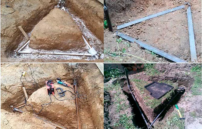
Installation work
For example, a scheme for connecting horizontal and vertical elements in the form of a triangle with sides of 2-3 m was chosen. This means that this shape with dimensions must be applied to the ground near the garage. You can right behind the wall. You can't do it in the basement.
Then either dig a trench or a triangular hole around the perimeter. The digging depth is 70-100 cm. Prepared electrodes are driven into the ground at the corners of the triangle to a depth of 0.5-1.0 m.
You cannot drill wells and place electrodes in them. Loose soil – high resistance. So just drive it in.Painting them is also prohibited.
A few recommendations:
- You can drive it in with a sledgehammer if the length of the vertical grounding conductors is 1-1.2 m. If it is longer, then you need to use a hammer drill or vibrator.
- If the length of the electrode is large, for example, 3 m, then it can be made in pieces, connecting them together with a threaded coupling. This will make it easier to hammer in without using a stepladder. You can weld elements, but a coupling is better.
- If the element being hammered rests against a hard object, for example, a stone, then there is no point in hammering. It is better to cut it off and drive a new one next to it. You can connect 2 rods, increasing the area of the ground electrode.
The electrodes are driven in, all that remains is to tie them. The steel strip can be welded to them or connected using bolts and nuts. The second option is better because welding in the ground is exposed to moisture, which causes it to begin to rust. The latter reduces contact, which means it increases resistance.
Bolts don't rust. But there is a possibility that they will loosen, so two nuts are screwed onto one bolt. One as a lock nut. The joints cannot be covered with soil - it must be located on the surface. The reason is the most vulnerable points in the garage grounding design. Therefore, they must always be in sight for maintenance and repairs.
A horizontal grounding conductor is installed from the garage to the triangular circuit along the shortest route. It is also secured with bolts or welding.
If the conductor can be laid openly inside the garage, then outside it can only be laid in the ground.
Now you need to check the resistance of the structure made. To do this, you can use a multimeter.If the garage resistance is greater than the standard, then it is worth adding several electrodes, driving them in so that they touch the horizontal jumpers. They need to be attached to them.
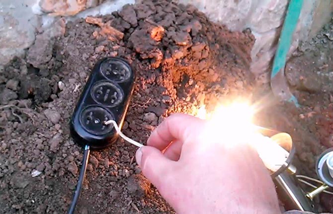
You can check resistance in different ways at home without using measuring instruments. For example, using a light bulb with a power of 100-200 W. It must be screwed into a socket, one wire of which is connected to ground, the other to phase. The bright light of the light bulb indicates that the ground loop is done correctly. If the light is dim, then there is a weak connection somewhere in the connections. It will have to be found and fixed.
The resistance should not change in any weather.
Inside the garage, the laid common conductor must be connected to the distribution panel. Better through RCD. It is from the connection point that the grounding wiring will be carried out to all power-consuming devices and equipment: sockets, lamps, drilling machine, welding machine And so on.
The last stage is backfilling the hole or trenches. The soil must be compacted well.
In a TT system, low resistance is excellent. In the TN-C-S system, this characteristic should not fall below 0.4 ohm. Because this indicator is a characteristic of the transformer. And if it is lower in the grounding of the garage, then the resistance of the overhead line laid from the substation will transfer to the garage circuit, which is not very good.
How to properly maintain garage grounding
Over time, the grounding created in the garage will lose its characteristics. A metal structure has only one end - destruction under the influence of natural loads. But the operating time can be extended if the circuit is periodically maintained:
- Once every six months, check the structure for breaks in its sections.
- You should also pay attention to the thickness of the installed elements. It should not decrease, because the smaller the thickness, the greater the resistance.
- Once every 12 years, check the grounding in the garage for resistance.
In fact, it is not difficult to organize grounding in the garage with your own hands. You just need to strictly follow the technical rules, instructions and recommendations, and pay special attention to safety precautions. If there is no confidence in the quality of the final result, then it is better to invite specialists.
Video about grounding in a garage with your own hands:
Dear readers, most of you have garages. Many of them have grinding and drilling machines that need to be grounded. Therefore, share your experience in the comments about who assembled the grounding loop and how. Save the article to your bookmarks so as not to lose useful recommendations.


I did linear grounding in my garage. Our garages are located right next to each other. There is a fence behind them. So there was no room. My neighbor and I decided to make a common outline. Therefore, we drove five corners into the ground and tied them with wire with a diameter of 10 mm. We checked the resistance - 10 ohms. The specialists said it was normal.
I did linear grounding in my garage. Our garages are located right next to each other. There is a fence behind them. So there was no room. My neighbor and I decided to make a common outline. Therefore, we drove five corners into the ground and tied them with wire with a diameter of 10 mm. We checked the resistance - 10 ohms. The specialists said it was normal.