Rules for connecting an RCD to a single-phase network with grounding: instructions for carrying out the work
Electrical energy is used widely and actively in the housing and economic sector. This is one of the main energy resources, the use of which, however, is completely unsafe.To ensure security, various protection methods are used.
In particular, connecting an RCD to a single-phase network with grounding prevents electric shock to a person, equipment breakdown, and fire of electrical wiring. But in order for the device to be able to perform these tasks, it is necessary to select the right protective device and correctly implement it into the electrical network.
Our article is devoted to solving these issues. We will tell you what parameters are important to consider when choosing an RCD, outline the requirements for installing the device, and also describe the procedure for connecting the device to a single-phase network.
The content of the article:
What protection measures does the RCD provide?
Of course, the introduction of protective devices into the power supply system is accompanied by certain rules. Let's consider these in relation to installation RCD.
The protective module from a series of similar devices is designed as a universal device, so most models are designed to protect against various negative manifestations during the use of electrical networks.
The RCD operates in three directions of protection:
- prevention of electric shock;
- breakdown of circuits with subsequent leakage of current to the equipment housing;
- electrical short circuit.
It should be noted: all three directions of protection work most effectively when the device is connected according to a grounded circuit.
In fact, a scheme without the participation of the “ground” is not excluded (and is often used). However, with this option, the efficiency of the device is significantly reduced.
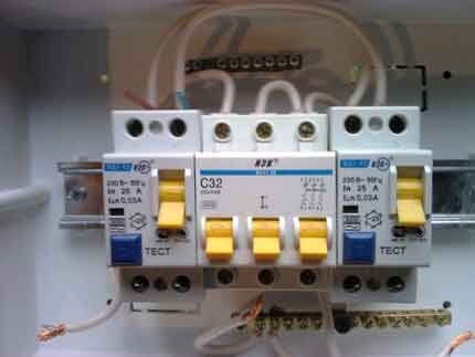
RCD devices are considered a mandatory component of electrical distribution panels for any purpose - permanently installed, temporary, portable.
Often they built into socket designs or plugs used to connect tools and household electrical appliances operated in damp, dusty conditions.
Selecting a device taking into account design parameters
The process of designing electrical installations by specialized design organizations should involve a rather complex task selection of suitable RCDs from the assortment of the electrical equipment market.
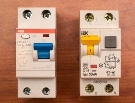
This task is really difficult. The modern market of electrical appliances, including RCDs, is distinguished by a unique assortment. This is the result of the lack of strict quality control on the part of government agencies.
There are a lot of different devices on the market, manufactured by a large number of manufacturers, many of which do not always adhere to current regulations.
The potential owner of the RCD has no choice but to accept the information provided by the device manufacturer. The guarantee is supplemented by a certificate of conformity and fire safety.
The absence of such documents for the product being sold is a direct ban on installation and operation, in accordance with the requirements of current standards.

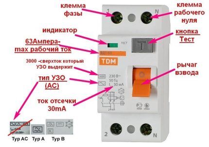
The choice of an RCD is always accompanied by taking into account the operating operational parameters and characteristics, which largely determine the quality and reliability of the device.
It is necessary to take into account the nominal indicators:
- tension;
- current;
- differential cut-off current.
These main characteristics must correspond to the technical parameters of the electrical installation being designed or the electrical circuit being operated.
The quality and reliability of an RCD is determined by certain indicators, the general physical meaning of which is often poorly understood.
These parameters are, first of all, the rated conditional short-circuit current and the rated making/breaking capacity current.
It is very rare that RCD manufacturers note all the noted characteristics in the documents for the devices. Therefore, it is necessary to correctly evaluate all the existing advantages and disadvantages of the selected devices.
From a technical design point of view, an RCD is traditionally characterized as a switching device whose operation is determined by the standby mode.The device does not have any features that help visually determine the quality of work.
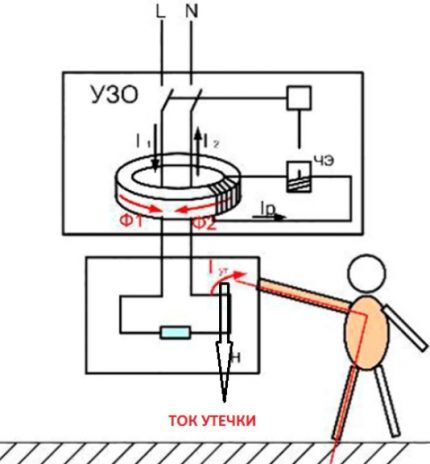
But there is a single principle on the basis of which such devices function in the same way. The device is connected to the operating current circuit and if a leakage current appears with a certain value exceeding the set value, the RCD simply opens the power circuit.
How correctly is the opening performed? It is possible to evaluate the performance of the device circuit, switching capacity, service life and other significant parameters only by specialized tests.
Rules for connecting the device
There are standards that define normal conditions for the installation and subsequent operation of RCDs. These standards are recorded, in particular, by documents GOST R 51326.1-99 and R 51327.1-99.
Therefore, the following criteria must be adhered to when using RCDs in practice:
- optimal ambient temperature range -5 + 40°C;
- relative air humidity value is not higher than 50% at +40°C and not higher than 90% at +20°C;
- limit value of altitude above sea level is 2000 m;
- absence of powerful magnetic fields in the immediate vicinity of the device.
As GOST R 50571.3-94 indicates, for connection diagrams in buildings, an important and necessary condition for the normal operation of an RCD as part of the electrical installation of a building is the absence in its area of action of any connection of the neutral working conductor with the grounded elements of the electrical installation and the “earth” protective conductor PE.
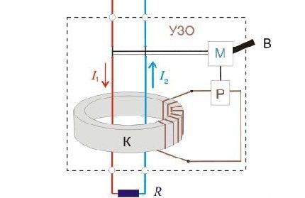
For the TN-C-S grounding system, in the distribution boards of electrical installations, at the points where the PEN conductor is separated, separate terminals or buses should be provided for the neutral working N and the neutral protective PE conductor.
Considering that the RCD device reacts to “ground” leakage of both the neutral and phase conductors, as a rule, it should be installed on the lines automatic safety switches.
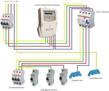
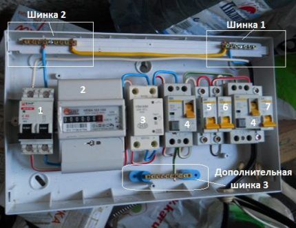
The introduction of automatic circuit breakers allows you to quickly determine the faulty section of the circuit by turning off individual lines one by one.
Thanks to the automatic machines, the dismantling of the ASU is eliminated when a faulty section is detected, including a section with a leak along the neutral conductor.
GOST R 50571.9-94 contains specific instructions aimed at performing actions to protect the zero working and zero protective conductors.
Carrying out work by professional services
Theoretically and practically, also with the participation of specialists, installing an RCD involves taking measures to determine the device’s response threshold.
There are established rules - a kind of instruction, where the entire sequence of actions in such cases is noted.
Work progress:
- First of all, the load circuit in phase and zero is disconnected from the device, for which an automatic switch is used.
- Next, a diagram of connecting measuring equipment and adjustment elements (potentiometer) to the RCD is used.
- By changing the resistance of the potentiometer, the device is activated and the current readings are recorded on the measuring device.
The marked value of the measuring device at the moment of operation is the differential current of the RCD. The recorded current reading must be within the specified range.
If the condition is not met, installation of a protective device in the circuit is prohibited. It is necessary to select another copy that matches the parameters.
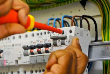
When connecting protective devices such as RCDs with grounding, the rules also require work aimed at measuring the leakage current within the boundaries of the device’s protection zone.
Typically, such measures are required for installation of electromechanical devices:
- The load is connected to the protection device through the circuit breaker.
- According to the test circuit, a measuring circuit consisting of a resistance store and an ammeter is connected to the device.
- By changing the resistance store, the device is activated and the ammeter readings are recorded.
- The leakage current is calculated using the formula: Iу = I – Ia, where I is the circuit breaking current, Ia is the ammeter reading.
The resulting value of Iу should not exceed the rated value of the differential current of the RCD by more than one third.

If such an excess is recorded, this is a clear sign that there is a defective area within the protection zone of the device. For such cases, the rules of the PES require the implementation of the necessary measures aimed at eliminating the leakage current.
Instruction for domestic installation
The introduction of RCDs into the electrical network for domestic purposes, provided that they are configured to the parameters of the electrical network, is carried out in compliance with a number of requirements.
List of mandatory rules:
- The device should be mounted on the input line and connected only after the circuit breaker. Usually the intermediate link between two devices is also an electricity meter.
- Installation work is carried out with the supply line completely de-energized.
- The rated current of the machine is selected equal to, or slightly less than, the value of the differential current of the device.
- Connections must be made in strict accordance with the manufacturer's designations and attached diagram.
- First of all, connections are made on the load side with the phase and neutral buses connected to the corresponding terminals of the device.
- Tighten the terminal screws with some force, sufficient to secure the connections, but without excessive force.
- Lastly, after checking the reliability of all connections and the absence of defects, the device is connected to the output terminals of the machine.
The attitude towards installation, configuration and commissioning of a protective device does not tolerate formalities. All actions must be carried out carefully, with accurate calculations and duplicate checks.
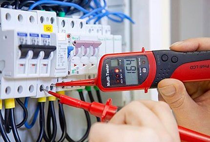
In the operating conditions of home household networks, they often try to resolve the issue connection of RCDs and automatic machines on your own.
However, this option does not guarantee security. You should always choose a professional installation - with the participation of specialists.
Conclusions and useful video on the topic
This video clearly explains and demonstrates how the protection device is included in the electrical circuit. Various schemes are being considered:
Having familiarized yourself with the rules for connecting an RCD and the procedure for performing work, as well as the features of installation in a single-phase network with grounding, you can try to do everything yourself.
However, this option is justified only if you have a configured protection device and certain skills in carrying out electrical work. Otherwise, the best solution would be to invite an electrician.
Do you have experience connecting an RCD yourself? Please tell readers about the nuances of choosing a suitable protection device and the features of its installation. Comment on the post, participate in discussions and add photos of your homemade products. The feedback block is located below.


