Calculation of cable cross-section by power and current: how to correctly calculate wiring
Are you planning to do modernization of the power grid or additionally extend the power line to the kitchen to connect a new electric stove? Here, minimal knowledge about the cross-section of the conductor and the effect of this parameter on power and current will be useful.
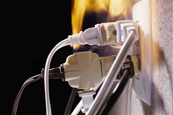
Agree that incorrect calculation of the cable cross-section leads to overheating and short circuit or to unjustified costs.
It is very important to carry out calculations at the design stage, since failure hidden wiring and subsequent replacement is associated with significant costs. We will help you understand the intricacies of calculations in order to avoid problems in the further operation of electrical networks.
In order not to burden you with complex calculations, we have selected clear formulas and calculation options, presented the information in an accessible form, and provided the formulas with explanations. Thematic photos and video materials have also been added to the article, allowing you to clearly understand the essence of the issue under consideration.
The content of the article:
Calculation of cross-section for consumer power
The main purpose of conductors is to deliver electrical energy to consumers in the required quantity. Since superconductors are not available under normal operating conditions, the resistance of the conductor material must be taken into account.
Calculation of the required section conductors and cables depending on the total power of consumers is based on long-term operating experience.
Let's begin the general course of calculations by first carrying out calculations using the formula:
P = (P1+P2+..PN)*K*J,
Where:
- P – the power of all consumers connected to the calculated branch in Watts.
- P1, P2, PN – power of the first, second, nth consumer, respectively, in Watts.
Having received the result at the end of the calculations using the above formula, it was time to turn to the tabular data.
Now you have to select the required section according to Table 1.

Stage #1 - calculation of reactive and active power
Consumer capacities are indicated in the equipment documents. Typically, equipment data sheets indicate active power along with reactive power.
Devices with an active type of load convert all received electrical energy, taking into account efficiency, into useful work: mechanical, thermal or another type.
Devices with active loads include incandescent lamps, heaters, and electric stoves.
For such devices, the calculation of power by current and voltage has the form:
P=U*I,
Where:
- P – power in W;
- U – voltage in V;
- I – current strength in A.
Devices with a reactive type of load are able to accumulate energy coming from a source and then return it. This exchange occurs due to the displacement of the current sinusoid and the voltage sinusoid.

Devices with reactive power include electric motors, electronic devices of all sizes and purposes, and transformers.

Electrical networks are built in such a way that they can transfer electrical energy in one direction from source to load.
Therefore, the returned energy from a consumer with a reactive load is parasitic and is wasted on heating the conductors and other components.
Reactive power depends on the phase angle between the voltage and current sinusoids. The phase shift angle is expressed through cosφ.
To find the total power, use the formula:
P = Q / cosφ,
Where Q – reactive power in VAR.
Typically, the device data sheet indicates reactive power and cosφ.
Example: the passport for the hammer drill indicates a reactive power of 1200 VAr and cosφ = 0.7.Therefore, the total power consumption will be equal to:
P = 1200/0.7 = 1714 W
If cosφ could not be found, for the vast majority of household electrical appliances cosφ can be taken equal to 0.7.
Stage #2 - search for simultaneity and margin coefficients
K – dimensionless simultaneity coefficient, shows how many consumers can be connected to the network at the same time. It rarely happens that all devices consume electricity at the same time.
Simultaneous operation of the TV and music center is unlikely. From established practice, K can be taken equal to 0.8. If you plan to use all consumers simultaneously, K should be set to 1.
J – dimensionless safety factor. Characterizes the creation of a power reserve for future consumers.
Progress does not stand still; every year new amazing and useful electrical devices are invented. Electricity consumption is expected to grow by 84% by 2050. Typically J is taken to be between 1.5 and 2.0.
Stage #3 - performing calculations using the geometric method
In all electrical calculations, the cross-sectional area of the conductor is taken - the cross-section of the core. Measured in mm2.
It is often necessary to learn how to correctly calculate wire diameter conductor wires.
In this case, there is a simple geometric formula for a monolithic round wire:
S = π*R2 = π*D2/4, or vice versa
D = √(4*S / π)
For rectangular conductors:
S = h * m,
Where:
- S – core area in mm2;
- R – core radius in mm;
- D – core diameter in mm;
- h, m – width and height, respectively, in mm;
- π — pi equals 3.14.
If you purchase a stranded wire, in which one conductor consists of many twisted wires of round cross-section, then the calculation is carried out according to the formula:
S = N*D2/1,27,
Where N – number of wires in the core.
Wires with cores twisted from several wires generally have better conductivity than monolithic ones. This is due to the peculiarities of current flow through a conductor with a round cross-section.
Electric current is the movement of like charges along a conductor. Like charges repel each other, so the charge distribution density is shifted towards the surface of the conductor.
Another advantage of stranded wires is their flexibility and mechanical resistance. Monolithic wires are cheaper and are mainly used for stationary installation.
Stage #4—calculate the power cross-section in practice
Task: the total power of consumers in the kitchen is 5000 W (meaning that the power of all reactive consumers has been recalculated). All consumers are connected to a single-phase 220 V network and are powered from one branch.

Solution:
Let us take the simultaneity coefficient K equal to 0.8. The kitchen is a place of constant innovation, you never know, the safety factor is J=2.0. The total estimated power will be:
P = 5000*0.8*2 = 8000 W = 8 kW
Using the value of the calculated power, we look for the nearest value in Table 1.
The closest suitable core cross-section for a single-phase network is a copper conductor with a cross-section of 4 mm2. Similar wire size with 6mm aluminum core2.
For single-core wiring, the minimum diameter will be 2.3 mm and 2.8 mm, respectively.In the case of using a multi-core option, the cross-section of the individual cores is summed up.
Calculation of current cross-section
Calculations of the required current and power cross-section of cables and wires will provide more accurate results.Such calculations make it possible to evaluate the overall influence of various factors on conductors, including thermal load, brand of wires, type of laying, operating conditions, etc.
The entire calculation is carried out in the following steps:
- selection of power of all consumers;
- calculation of currents passing through a conductor;
- selection of a suitable cross-section using tables.
For this calculation option, the power of consumers in terms of current and voltage is taken without taking into account correction factors. They will be taken into account when summing the current strength.
Stage #1 - calculation of current strength using formulas
For those who have forgotten the school physics course, we offer the basic formulas in the form of a graphic diagram as a visual cheat sheet:

Let us write down the dependence of the current I on the power P and line voltage U:
I = P/Ul,
Where:
- I — current strength, taken in amperes;
- P — power in watts;
- Ul — line voltage in volts.
Line voltage generally depends on the power supply source; it can be single- or three-phase.
Relationship between linear and phase voltage:
- Ul = U*cosφ in case of single-phase voltage.
- Ul = U*√3*cosφ in case of three-phase voltage.
For household electrical consumers, cosφ=1 is accepted, so the linear voltage can be rewritten:
- Ul = 220 V for single-phase voltage.
- Ul = 380 V for three-phase voltage.
Next, we summarize all consumed currents using the formula:
I = (I1+I2+…IN)*K*J,
Where:
- I – total current in amperes;
- I1..IN – current strength of each consumer in amperes;
- K – simultaneity coefficient;
- J – safety factor.
The coefficients K and J have the same values as those used when calculating the total power.
There may be a case when in a three-phase network a current of unequal strength flows through different phase conductors.
This happens when single-phase and three-phase consumers are connected to a three-phase cable at the same time. For example, a three-phase machine and single-phase lighting are powered.
A natural question arises: how is the cross-section of a stranded wire calculated in such cases? The answer is simple - calculations are made based on the most loaded core.
Stage #2 - selecting a suitable section using tables
The operating rules for electrical installations (PEU) contain a number of tables for selecting the required cross-section of the cable core.
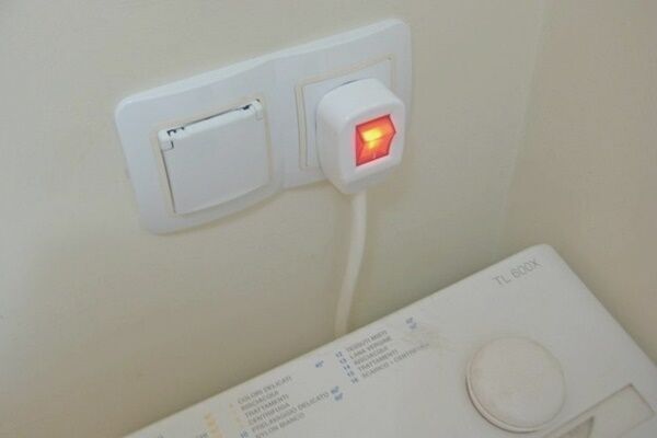
The conductivity of a conductor depends on temperature. For metal conductors, resistance increases with increasing temperature.
When a certain threshold is exceeded, the process becomes self-sustaining: the higher the resistance, the higher the temperature, the higher the resistance, etc. until the conductor burns out or causes a short circuit.
The next two tables (3 and 4) show the cross-section of conductors depending on currents and installation method.

A cable differs from a wire in that all cable cores, equipped with their own insulation, are twisted into a bundle and enclosed in a common insulating sheath. More details about the differences and types of cable products are written in this article.

When using tables, the following coefficients are applied to the permissible continuous current:
- 0.68 if 5-6 cores;
- 0.63 if 7-9 cores;
- 0.6 if 10-12 cores.
Reduction factors are applied to current values from the “open” column.
The neutral and grounding conductors are not included in the number of conductors.
According to PES standards, the selection of the cross-section of the neutral conductor according to the permissible continuous current is made as at least 50% of the phase conductor.
The next two tables (5 and 6) show the dependence of the permissible long-term current when laying it in the ground.

The current load when laid openly and when laid deep into the ground differs. They are accepted as equal if laying in the ground is carried out using trays.

For the installation of temporary power supply lines (carrying, if for private use), the following table (7) applies.

When laying cables in the ground, in addition to the heat dissipation properties, it is necessary to take into account the resistivity, which is reflected in the following table (8):

Calculation and selection of copper cores up to 6 mm2 or aluminum up to 10 mm2 is carried out as for continuous current.
In the case of large cross-sections, it is possible to apply a reduction factor:
0.875 * √Tpv
Where Tpv — ratio of switching duration to cycle duration.
The duration of switching on is taken to be no more than 4 minutes. In this case, the cycle should not exceed 10 minutes.
When choosing a cable for distributing electricity in wooden house Particular attention is paid to its fire resistance.
Stage #3 - calculation of the current cross-section of the conductor using an example
Task: calculate the required section copper cable for connection:
- three-phase woodworking machine with a power of 4000 W;
- three-phase welding machine with a power of 6000 W;
- household appliances in the house with a total power of 25,000 W;
The connection will be made with a five-core cable (three phase conductors, one neutral and one grounding), laid in the ground.

Solution.
Step 1. We calculate the linear voltage of a three-phase connection:
Ul = 220 * √3 = 380 V
Step #2. Household appliances, a machine tool and a welding machine have reactive power, so the power of the machinery and equipment will be:
Pthose = 25000 / 0.7 = 35700 W
Pobor = 10000 / 0.7 = 14300 W
Step #3. Current required to connect household appliances:
Ithose = 35700 / 220 = 162 A
Step #4. Current required to connect equipment:
Iobor = 14300 / 380 = 38 A
Step #5. The required current for connecting household appliances is calculated based on one phase. According to the problem, there are three phases. Therefore, the current can be distributed among the phases. For simplicity, we assume a uniform distribution:
Ithose = 162 / 3 = 54 A
Step #6. Current per phase:
If = 38 + 54 = 92 A
Step #7. Equipment and household appliances will not work at the same time; in addition, we will set aside a reserve of 1.5. After applying correction factors:
If = 92 * 1.5 * 0.8 = 110 A
Step #8. Although the cable contains 5 cores, only three phase cores are taken into account. According to Table 8 in the column three-core cable in the ground, we find that a current of 115 A corresponds to a core cross-section of 16 mm2.
Step #9. According to Table 8, we apply a correction factor depending on the characteristics of the land. For a normal type of earth, the coefficient is 1.
Step #10. Optional, calculate the diameter of the core:
D = √(4*16 / 3.14) = 4.5 mm
If the calculation were made only based on power, without taking into account the peculiarities of cable laying, then the cross-section of the core would be 25 mm2. Calculating current strength is more complicated, but sometimes allows you to save significant money, especially when it comes to multi-core power cables.
You can read more about the relationship between voltage and current values here.
Voltage drop calculation
Any conductor, except superconductors, has resistance. Therefore, if the cable or wire is long enough, a voltage drop occurs.
PES standards require that the cross-section of the cable core be such that the voltage drop is no more than 5%.

This primarily concerns low-voltage cables of small cross-section.
The voltage drop calculation is as follows:
R = 2*(ρ * L) / S,
Upad = I * R,
U% = (Upad /ulin) * 100,
Where:
- 2 – coefficient due to the fact that the current necessarily flows through two wires;
- R – conductor resistance, Ohm;
- ρ — conductor resistivity, Ohm*mm2/m;
- S – conductor cross-section, mm2;
- Upad – drop voltage, V;
- U% - voltage drop relative to Ulin,%.
Using formulas, you can independently perform the necessary calculations.
Carrying calculation example
Task: calculate the voltage drop for a copper wire with a cross-section of one core of 1.5 mm2. The wire is required to connect a single-phase electric welding machine with a total power of 7 kW. Wire length 20 m.

Solution:
Step 1. We calculate the resistance of the copper wire using Table 9:
R = 2*(0.0175 * 20) / 1.5 = 0.47 Ohm
Step #2. Current flowing through the conductor:
I = 7000 / 220 = 31.8 A
Step #3. Voltage drop on the wire:
Upad = 31.8 * 0.47 = 14.95 V
Step #4. We calculate the percentage of voltage drop:
U% = (14,95 / 220) * 100 = 6,8%
Conclusion: to connect the welding machine, a conductor with a large cross-section is required.
Conclusions and useful video on the topic
Calculation of the conductor cross-section using the formulas:
Recommendations from specialists on the selection of cable and wire products:
The above calculations are valid for copper and aluminum conductors for industrial use. For other types of conductors, the total heat transfer is pre-calculated.
Based on these data, the maximum current that can flow through the conductor without causing excessive heating is calculated.
If you have any questions about the method for calculating the cable cross-section or would like to share your personal experience, please leave comments on this article.The review section is located below.


To be honest, I didn’t understand who this article was intended for... so much theoretical material. In everyday practice, when choosing the cross-section of wires, a person is interested in the approximate load power, that is, it is necessary to know the current strength and what cross-section of the wire or cable should be taken based on the expected load. One table of wire cross-sections and current load would be enough. Some advice on how to correctly determine the wire cross-section would be helpful.
Still, I didn’t understand how to find the permissible wire length and calculate the resistance of the same wire.
Excellent post on calculating the cable cross-section, the first time I saw one like this, I bookmarked it. (You definitely need to know the theory of what and where it comes from.) But in my opinion, it’s too complicated for a novice electrician and an independent home owner. For practical calculations, I use programs that are quite good, in my opinion: there are very simple options for approximate calculations and more complex ones, with an increased number of specified parameters. And this, as a rule, is quite enough.
For those who have the appropriate education, the article is good, so to speak, “to take note.” But for people who just want to choose a wire size for their home wiring, there is too much information. The main thing is to follow the basic rules when calculating - always take with a reserve. And so that the machine to which the selected wire goes corresponds to the permissible current. Otherwise, it happens that the wire has already melted, and the machine didn’t even think about cutting it off.
The article, conceived as a manual for the master for calculating home electrical networks, contains a large amount of reference data, I would say, even very large. Why overload the human brain with unnecessary information? For each electrical appliance used in everyday life, the rated power is indicated (in the instructions or on the back wall). And in our apartments there is a usual, almost standard set: a refrigerator (two), an electric stove, a TV (three or four), a computer (laptop), and so on. That is, we have all the data to calculate the network. We will set aside 50% for future acquisitions. That's all! We take the permissible current load to be 10A, not 20, the wires will not heat up.
Now the most important thing! The author confused active and reactive power!!! Active power is consumed by: wires, heaters, modern TVs, computers, energy-saving and LED light bulbs and welding machines (Sic!). And reactive power is the domain of capacitors and inductors, of which there are practically none left in modern houses, so it can be ignored. For information, electricity meters keep track of ACTIVE POWER. The mythical cos f for a house is practically equal to one (for 0.7 it would have been that much earlier). The last thing I wanted to say is, try to use single-core copper wires and cables; their connection in the terminal blocks does not weaken over time, which cannot be said about multi-core ones. I hope I made things easier for someone.
In my case, the above tables are not valid. The situation is that with a three-phase network, the voltage is 380 V, the power is 198 kW, the cable cross-section is 4x185 mm2, the cable heats up more than normal, although according to the table, this cable cross-section should withstand the greatest power
Tell me, why did you indicate such a cable cross-section in general in the table, because there is a difference in the method of laying the cable, and therefore the cable cross-section changes, according to your table I can connect El. A slab with a power of 16.8 kW for 2.5 copper 3 phases, when the cable runs hidden in the pipe and plus the length, losses!!!