Connection diagrams for a magnetic starter for 220 V and 380 V + features of independent connection
A magnetic starter is a device responsible for the uninterrupted operation of equipment that meets standard requirements. It is used to distribute the supply voltage and control the operation of connected loads.
Most often, power is supplied to electric motors through it. And through it the engine is reversed and stopped. All these manipulations will be made possible by the correct connection diagram for the magnetic starter, which you can assemble yourself.
In this material we will talk about the design and operating principles of a magnetic starter, and also understand the intricacies of connecting the device.
The content of the article:
The difference between a magnetic starter and a contactor
Often, when selecting a switching device, confusion arises between magnetic starters (MF) and contactors. These devices, despite their similarity in many characteristics, are still different concepts. A magnetic starter combines a number of devices; they are connected in one control unit.
The MP may include several contactors, plus protective devices, special attachments, and control elements. All this is enclosed in a housing that has some degree of moisture and dust protection.These devices are mainly used to control the operation of asynchronous motors.
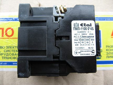
A contactor is a monoblock device with a set of functions provided for by a specific design. While starters are used in quite complex circuits, contactors are mainly found in simple circuits.
Design and purpose of the device
Having compared the connection of the MP and the contactor, we can conclude that the first device differs from the second in that it is used to start an electric motor. You can even say that the MP is the same contactor with which an electric motor is controlled.
The difference is so arbitrary that recently many manufacturers have called MPs AC contactors, but with small dimensions. And the constant improvement of contactors has made them universal, so they have become multifunctional.
Purpose of the magnetic starter
MFs and contactors are built into power networks that transport current with alternating or direct voltage. Their action is based on electromagnetic induction.
The device is equipped with signal contacts and those through which power is supplied. The first are called auxiliary, the second - workers.
MPs remotely control electrical installations, including electric motors.Their role as protection is zero - only the voltage disappears or at least drops to a limit below 50%, the power contacts open.
After stopping the equipment in which the contactor is built into the circuit, it will never turn on on its own. To do this, you will have to press the “Start” key.
For safety, this is a very important point, since accidents caused by spontaneous switching on of an electrical installation are completely excluded.
Starters, the circuit of which includes thermal relays, protect the electric motor or other installation from prolonged overloads. These relays can be double-pole (TPN) or single-pole (SRP). Triggering occurs under the influence of motor overload current flowing through them.
Design and operation of the device
For the MP to operate correctly, it is necessary to adhere to certain installation rules, have an understanding of the basics of relay technology, and correctly select the equipment power supply circuit.
Since the devices are designed to operate over a short period of time, the most popular are MPs with usually open contacts. MP series PME and PAE are in greatest demand.
The first ones are built into signal circuits for electric motors with a power of 0.27 - 10 kW. The second - with a power of 4 - 75 kW. They are designed for voltage 220, 380 V.
There are four options:
- open;
- protected;
- dust and waterproof;
- dust-splashproof.
PME starters include a two-phase TRN relay in their design. In a PAE series starter, the number of built-in relays depends on the size.
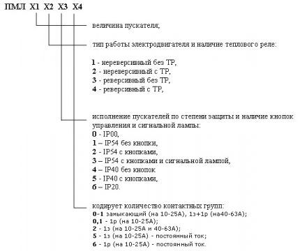
At about 95% of the rated voltage, the starter coil is capable of providing reliable operation.
The MP consists of the following main units:
- core;
- electromagnetic coil;
- anchors;
- frame;
- mechanical work sensors;
- groups of contactors - central and additional.
The design may also include, as additional elements, a protective relay, electrical fuses, an additional set of terminals, and a starting device.
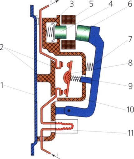
Essentially, this is a relay, but it cuts off a much larger current. Since the electromagnets of this device are quite powerful, it has a high response speed.
An electromagnet in the form of a coil with a large number of turns is designed for a voltage of 24 - 660 V. Which is located on the core, more power is needed to overcome the spring force.
The latter is designed for quick disconnection of contacts, the speed of which determines the magnitude of the electric arc. The faster the opening occurs, the smaller the arc and the better condition the contacts themselves will be.
Normal state when contacts are open. At the same time, the spring holds the upper section of the magnetic circuit in a raised state.
When power is supplied to the magnetic starter, current passes through the coil and creates an electromagnetic field.It attracts the mobile part of the magnetic circuit by compressing the spring. The contacts close, power is supplied to the load, and as a result, it starts working.
If the power supply to the MP is turned off, the electromagnetic field disappears. Straightening up, the spring gives a push, and the upper part of the magnetic circuit appears at the top. As a result, the contacts diverge and power to the load is lost.
Some starter models are equipped with surge suppressors, which are used in semiconductor control systems.
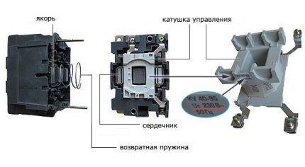
After connecting the magnetic starter, the control coil is powered by alternating current, but for this device the type of current does not matter.
Starters are usually equipped with two types of contacts: power and blocking. Through the former, the load is connected, and the latter protects against incorrect actions when connecting.
There can be 3 or 4 pairs of power MPs, it all depends on the design of the device. Each pair has both mobile and fixed contacts connected to the terminals located on the body via metal plates.
The first differ in that the load is constantly supplied with power. Removal from the operating state occurs only after the starter is triggered.
Contactors with normally open contacts are supplied with power only while the starter is operating.
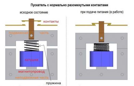
Normally closed ones differ in that the load is constantly supplied with power, and disconnection occurs only after the starter is triggered. Contactors with normally open contacts are supplied with power only while the starter is operating.
Starter installation features
Incorrect installation of the magnetic starter can have consequences in the form of false alarms. To avoid this, you should not select areas subject to vibration, shock, or shock.
Structurally, the MP is designed in such a way that it can be mounted in an electrical panel, but in compliance with the rules. The device will work reliably if its installation location is on a straight, flat, and vertical surface.
Thermal relays should not be heated by extraneous heat sources, which will negatively affect the operation of the device. For this reason, they should not be placed in areas exposed to heat.
It is strictly forbidden to install a magnetic starter in a room where devices with a current of 150 A or more are installed. Turning such devices on and off causes a quick shock.
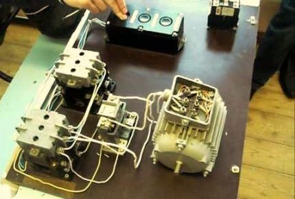
To prevent distortion of the spring washers located in the contact terminal of the starter, the end of the conductor is bent in a U-shape or into a ring. When you need to connect 2 conductors to a clamp, you need their ends to be straight and on both sides of the clamping screw.
Putting the starter into operation must be preceded by an inspection, checking the serviceability of all elements.Moving parts must be moved by hand. Electrical connections must be checked against the diagram.
Popular MP connection diagrams
The most commonly used wiring diagram is with one device. To connect its main elements use a 3-core cable and two open contacts if the device is turned off.
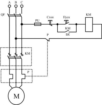
Under normal circumstances, relay contact P is closed. When you press the "Start" key, the circuit closes. Pressing the “Stop” button disassembles the circuit. In case of overload, the thermal sensor P will operate and break contact P, the machine will stop.
With this scheme, the rated voltage of the coil is of great importance. When the voltage on it is 220 V, the motor is 380 V, in the case of a star connection, such a circuit is not suitable.
For this purpose, a circuit with a neutral conductor is used. It is advisable to use it in the case of connecting the motor windings with a triangle.
Subtleties of connecting a 220 V device
Regardless of how it is decided to connect the magnetic starter, the project must have two circuits - power and signal. Voltage is supplied through the first, and the operation of the equipment is controlled through the second.
Features of the power circuit
Power for the MP is connected through contacts, usually designated by the symbols A1 and A2. They receive a voltage of 220 V, if the coil itself is designed for such voltage.
It is more convenient to connect the “phase” to A2, although there is no fundamental difference in the connection. The power source is connected to the contacts located lower on the housing.
The type of voltage does not matter, the main thing is that the rating does not go beyond 220 V.
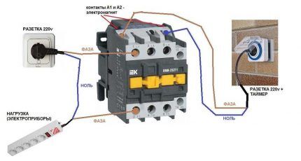
The disadvantage of this connection option is that to turn it on or off you need to manipulate the plug. The circuit can be improved by installing an automatic machine in front of the MP. It is used to turn the power on and off.
Changing the control circuit
These changes do not affect the power circuit; in this case, only the control circuit is upgraded. The whole scheme as a whole undergoes minor changes.
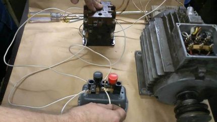
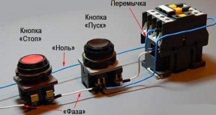
The keys are built in series in front of the MP. The first one is “Start”, followed by “Stop”. The contacts of the magnetic starter are manipulated by means of a control pulse.
Its source is the pressed start button, which opens the path for supplying voltage to the control coil. “Start” does not have to be kept on.
It is supported by the principle of self-capture. It consists in the fact that additional self-locking contacts are connected in parallel to the “Start” button. They supply voltage to the coil.
After they are closed, the coil is self-energized. A break in this circuit results in the MP being turned off.
The stop button is usually red. The start button can have not only the inscription “Start”, but also “Forward” and “Back”. Most often it is green, although it can also be black.
Connection to 3-phase network
It is possible to connect 3-phase power through an MP coil operating from 220 V. Typically, the circuit is used with an asynchronous motor. The signal circuit does not change.
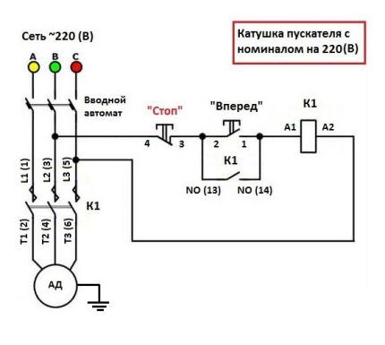
The power circuit has differences, but not very significant. Three phases are supplied to the inputs indicated on the plan as L1, L2, L3. The three-phase load is connected to T1, T2, T3.
Input into the thermal relay circuit
In the gap between the magnetic starter and the asynchronous electric motor, a thermal relay is connected in series. The choice is made depending on the type of motor.
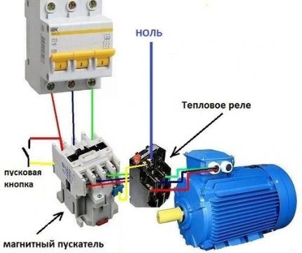
Connect the relay to the terminal with the magnetic starter. The current in it passes to the motor in series, simultaneously heating the relay. The top of the relay is equipped with additional contacts integrated with the coil.
Relay heaters are designed to accommodate the maximum amount of current flowing through them. They do this so that when the engine is in danger due to overheating, the relay can turn off the starter.
We also recommend reading our other article where we talked about how to select and connect a 380 V electromagnetic starter. For more details, go to link.
Starting the motor in reverse
For individual equipment to function, it is necessary that the motor can rotate both left and right.
The connection diagram for this option contains two MPs, a push-button station or three separate keys - two starting ones “Forward”, “Back” and “Stop”.
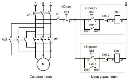
From short circuit the power circuit is protected by normally closed contacts KM1.2, KM2.2.
The circuit is prepared for operation as follows:
- Turn on AB QF1.
- The power contacts of MP KM1, KM2 receive phases A, B, C.
- The phase that supplies the control circuit (A) through SF1 (signal circuit breaker) and the SB1 “Stop” key is supplied to contact 3 (keys SB2, SB3), contact 13NO (MP KM1, KM2).
Next, the circuit operates according to an algorithm depending on the direction of rotation of the motor.
Engine reverse control
Rotation begins when the SB2 key is activated. In this case, phase A is supplied through KM2.2 to the MP coil KM1. The starter starts turning on with the closing of the normally open contacts and the opening of the normally closed ones.
The closure of KM1.1 provokes self-catching, and the closing of the KM1 contacts is followed by the supply of phases A, B, C to identical contacts of the motor windings and it begins to rotate.
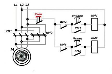
The action taken will disconnect the circuit, control phase A will no longer be supplied to the KM1 inductor, and the core with contacts will be restored to its original position by means of a return spring.
The contacts will disconnect and the voltage supply to the motor M will stop. The circuit will be in standby mode.
It is launched by pressing the SB3 button. Phase A through KM1.2 will go to KM2, MP, will work and through KM2.1 will be self-retaining.
Next, the MP, through contacts KM2, will swap the phases. As a result, the motor M will change the direction of rotation. At this time, the KM2.2 connection, located in the circuit supplying the KM1 MP, will be disconnected, preventing KM1 from being turned on while KM2 is functioning.
Power circuit operation
The responsibility for switching phases to redirect the rotation of the motor rests with the power circuit.
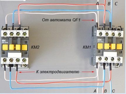
When the contacts of MP KM1 are triggered, the first winding receives phase A, the second winding receives phase B, and the third receives phase C. In this case, the motor rotates to the left.
When KM2 is triggered, phases B and C are relocated. The first goes to the third winding, the second to the second. There are no changes in phase A. The engine will begin to rotate to the right.
Conclusions and useful video on the topic
Details about the device and connection of the contactor:
Practical assistance in connecting MP:
Using the diagrams above, you can connect a magnetic starter with your own hands to both a 220 and 380 V network.
It must be remembered that the assembly is not difficult, but for the reversible circuit it is important to have double-sided protection, which makes reverse connection impossible. In this case, the blocking can be either mechanical or through blocking contacts.
If you have any questions about the topic of the article, please leave your comments in the block below.There you can provide interesting information or give advice on connecting magnetic starters to visitors to our site.


