Pressure switch for compressor: device, marking + connection diagram and adjustment
The use of an air pneumatic relay allows you to automate the filling of the compressor receiver with compressed gas. The operator of equipment with a pressure switch does not need to monitor the process, trying to fix the limit parameters. As a result, engine damage is prevented. Significant results, right?
If you are planning to purchase a pressure switch for your compressor, then you have come to the right place. Here you will find a vast amount of extremely useful information about the principles of operation of the device, its configuration and connection methods.
We have described in detail the existing types of pneumatic relays. They provided options for connecting to a household and industrial network with extremely clear diagrams. We looked at typical breakdowns and ways to prevent them. The information and useful tips we provide are supplemented with graphic, photo and video applications.
The content of the article:
- Operating principle of a pressure switch
- Complete set of compressor automation unit
- Types of pressure switch devices
- Structure of pneumatic relay symbols
- Air relay connection diagrams
- Installation of relays and auxiliary elements
- Adjustment and commissioning process
- Possible malfunctions of the device
- Troubleshooting methods
- Conclusions and useful video on the topic
Operating principle of a pressure switch
The name of the relay is determined by its purpose - controlling a piston compressor to maintain the required atmospheric pressure in the receiver. It is rarely found on a screw type device responsible for compressing and supplying air.
I take into account the magnitude of the pressing force in pneumatic automation; the device acts on the voltage line, closing or opening it. Thus, insufficient pressure in the compressor starts the motor, and when the required level is reached, it turns it off.
This standard operating principle, based on connecting a normal closed loop to a circuit, is used to control the motor.

Modifications with the opposite operating algorithm are also presented: when reaching minimum values in the compression circuit, the pressure switch turns off the electric motor, and at maximum values it activates. Here the system operates in a normally open loop.
The operating system is made up of spring mechanisms with varying degrees of rigidity, reproducing the response to fluctuations in the air pressure unit.
During operation, the indicators formed as a result of the elastic force of tension or compression of the springs and the pressure of the atmosphere pressed by the device are compared. Any changes automatically activate the action of the spiral and the relay unit connects or disconnects the electricity supply line.
However, it is worth considering that the design of the review model does not provide for regulatory influence. Exceptional impact on the engine. In this case, the user has the opportunity to set a peak value, upon reaching which the spring will fire.
Complete set of compressor automation unit
The relay design is a small-sized block equipped with receiving pipes, a sensing element (spring) and a membrane. Mandatory subassemblies include an unloading valve and a mechanical switch.
The pressure switch sensing unit is made up of a spring mechanism, the compression force of which is changed by a screw. According to the factory standardized settings, the elasticity coefficient is set to a pressure in the pneumatic chain of 4-6 at, as reported in the instructions for the device.

The degree of rigidity and flexibility of the spring elements is subject to the temperature of the environment, therefore absolutely all models of industrial devices are designed for stable operation in an environment from -5 to +80 ºC.
The reservoir membrane is connected to the relay switch. During movement, it turns the pressure switch on and off.

The unloading element is located between the ejector check valve and the compression block. If the motor drive stops working, the unloading section is activated, through which excess pressure (up to 2 atm) is released from the piston compartment.
With further start or acceleration of the electric motor, a pressure is created that closes the valve.This prevents overloading of the drive and simplifies starting the device in switched off mode.
There is an unloading system with a time interval of activation. The mechanism remains in the open position when the engine starts for a specified period. This range is enough for the engine to achieve maximum torque.
A mechanical switch is required to start and stop the automatic system options. As a rule, it has two positions: “on.” and "off". The first mode turns on the drive and the compressor operates according to the established automatic principle. The second one prevents accidental starting of the engine, even when the pressure in the pneumatic system is low.

Safety in industrial structures must be at a high level. For these purposes, the compressor regulator is equipped with a safety valve. This ensures system protection in the event of incorrect relay operation.
In emergency situations, when the pressure level is higher than the permissible norm, and the telepressostat does not work, the safety unit comes into operation and vents the air. They operate according to a similar scheme safety valves in heating systems, the operating principles and devices of which are described in our recommended article.
Optionally, the viewing device can also be used as additional safety equipment. thermal relay. With its help, the strength of the supply current is monitored for timely disconnection from the network when parameters increase.
To avoid burnout of the motor windings, the power is turned off. The nominal values are set using a special control device.
Types of pressure switch devices
There are only two variations in the design of the automatic compressor unit. The determination is made based on their operating principle. In the first version, the mechanism turns off the electric motor when the established limits of the air mass pressure level in the pneumatic network are exceeded. These devices are called normally open.

Another model with the opposite principle - turns on the engine if a drop in pressure is detected below the permissible level. Devices of this type are called normally closed.
Structure of pneumatic relay symbols
The marking of the air pressure switch indicates the entire optional set of the device, design features, including information about the factory settings for the pressure differential.

Let us examine the designations in more detail using the example of devices for air ejectors RDK – (*) (****) – (*)/(*):
- RDK – series of relays for compressors;
- (*) – number of threaded ports: 1 – one port with 1/4”NPT internal thread; 4 – four connectors;
- (****) - type of housing design: T10P - version 10 with a “lever” switch; T10K – “button” switch; T18P – execution 18 with a “switch” switch; T19P - 19 s;
- (*) – factory settings of the threshold response: 1 – 4…6 bar; 2 – 6…8 bar; 3 – 8…10 bar;
- (*) – diameter of the unloading valve: the absence of a symbol means a standardized parameter of 6 mm; 6.5 mm – 6.5 mm.
The difference between the minimum and maximum pressure thresholds is set by the manufacturer and, as a rule, has a value of 2 bar.
However, it is also possible to manually adjust the range of two values – maximum and minimum, but only downwards.
The specifics of setting up pressure switches for pumping stations are outlined in next article, the contents of which we advise you to familiarize yourself with.
Air relay connection diagrams
The compressor pressure switch is manufactured for connection to electrical circuits of different loads. In accordance with the rating of the power supply line, the appropriate model of the relay unit is selected.
Option #1: to a network with a nominal value of 220 V
If the drive motor is a single-phase device, then a 220 V relay with two groups of contacts is installed.

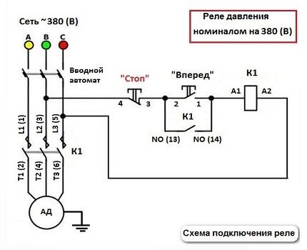
Option #2: to a three-phase network with a voltage of 380 V
For a three-phase load of a 380 V circuit, one of the options can be used: a modification of the relay for 220 V or 380 V, with three contact lines, to simultaneously disconnect all three phases.
Both methods have different schemes. Let's consider the first option:
By choosing the second method, power is supplied from one phase (zero) and in this case the relay rating should be 220 V. For more details, see the following diagram:

After connecting to the power supply, you need to understand the additional capabilities provided in the air blocks for ejectors.
Installation of relays and auxiliary elements
In some modifications of pressure switches, you can find additional equipment in the form of flange connections, through which additional equipment is connected. These are mainly three-way parts, with a ¼-inch diameter.

To put the device into operation, it must be connected to the receiver. Installation consists of the following steps:
- The device is connected to the compressor through the main outlet.
- A pressure gauge is connected to the device with flanges. There may also be other auxiliary mechanisms that require activation: a safety or unloading valve.
- Channels that are not used for connection must be closed with plugs.
- Next, according to the electrical diagram, the relay is connected to the contacts of the motor control circuit.
Motors with low power can be connected directly; in other cases, additional installation of an electromagnetic starter of appropriate power is required.
Before moving on to setting the threshold response parameters, it is worth paying attention to the operating conditions. First, adjustments are made under pressure. Secondly, the electrical supply to the engine must be cut off.
Adjustment and commissioning process
Factory set parameters do not always meet consumer requirements. In most cases, this is due to insufficient compression force at the highest point of disassembly.
The operating range of the pressure switch may also not be suitable. In this case, independent adjustment of the actuator will be relevant.

To begin setting the operating compression value, you will need to inspect the engraved plate, which indicates the parameters of the electric motor and compressor.
We only need the largest value that the device produces. This indicator indicates the maximum pressure force that can be set on the relay for the correct operation of the entire pneumatic system.
If you set the specified value (in the figure 4.2 atm), then taking into account all factors - differences in power supply, exhaustion of the service life of parts, etc. - the compressor may not reach the maximum pressure, and accordingly it will not turn off.
In this mode, the working elements of the equipment will begin to overheat, then deform and eventually melt.

For reliable operation without shutdowns, it is necessary to set the highest shutdown pressure on the relay, which does not reach the nominal value engraved on the compressor, namely 0.4-0.5 atm lower. According to our example - 3.7-3.8 atm.

Having determined the level that will be set, it is necessary to remove the relay housing. Under it there are two adjusting elements - a small and a large nut (in Figure 1.3).
Nearby there are arrow indicators for the direction in which the twists will be made - thereby compressing and unclenching the spring mechanism (2.4).
A large screw clamp and spring are provided to control compression settings. When twisted clockwise, the spiral compresses - the compressor switch-off pressure increases. Reverse adjustment - weakens, and accordingly, the pressure level for shutdown decreases.

When reproducing settings, the receiver must be at least 2/3 full.
Having understood the purpose of the elements, let's proceed:
- To ensure the proper level of safety, we turn off the power supply.
- Changing the compression level of the springs is done by turning the nut several turns in the required direction. On the board, near the large-diameter adjusting screw, according to the standards, there is a symbol in Latin letters P (Pressure), a smaller one - ΔР.
- The adjustment process is monitored visually on a pressure gauge.
For convenience, some manufacturers place the adjusting fittings for changing the nominal value on the surface of the device body.
Possible malfunctions of the device
Several malfunctions characteristic of pressure switches are noted. In most cases, they are simply replaced with new devices. However, there are minor problems that you can fix yourself without the help of a repairman.

The most common malfunction is characterized by air leakage from the relay when the receiver is turned on. In this case, the culprit may be the start valve. It is enough to replace the gasket and the problem will be eliminated.
Frequent starting of the compressor indicates loosening and displacement of the adjusting bolts. Here you will need to double-check the threshold for turning on and off the relay and adjust them according to the instructions in the previous section.
Troubleshooting methods
A more difficult problem lies ahead if the compressor does not work. There may be several sources. Let's consider one of them - melting of the pressure switch contacts due to erosion arising from electrical sparks.

To eliminate this type of malfunction, you can use one of the following methods: clean the surface, which extends the service life by at least 3 months, or repair it by replacing the contacts in the terminal clamps.
Step-by-step instructions for the second option:
- Bleed all air from the receiver and turn off the power to the ejector. Remove the pressure switch.
- Having removed the protective housing, disconnect the wiring connected to the group of contacts.
- Using a screwdriver, you need to remove the terminal with contacts and drill out the burnt lines from it.
- You can replace the wire with copper wire. It is necessary to select it taking into account the diameter of the hole, since it must fit tightly into the seat. It is inserted into the hole and pressed on both sides.
- Similar actions are performed with the remaining burnt lines.
- After the contact group is assembled, it is mounted in its original place and the pressure switch cover is screwed on.
The compressor relay operates in difficult conditions, subject to wear and failure.
Although the repair is not cost-effective, those familiar with the device can perform the repair themselves. However, the option of replacing it with a new device still remains profitable.
Conclusions and useful video on the topic
Details about the design of the pressure switch, as well as a visual process for adjusting its parameters in the plot:
It is also possible to independently assemble the control unit for the compressor; see this video:
Pneumatic devices are considered safer and easier to use than electric or gasoline models. There is a wide selection of additional equipment that works with compressed air: guns for washing, inflating tires or painting and many others.
With the help of a relay, it becomes possible to operate automatically while maintaining the required compression level in the receiver.
Please write comments in the block form located under the article test. Share your own experience in operating a compressor with a pressure switch, ask questions, post photos on the topic. It is possible that your recommendations will be useful to site visitors.


