Calculation of air ducts by speed and flow + methods for measuring indoor air flow
Balanced air exchange is the basis for people’s well-being and ability to work.Is not it? But in order to create comfortable conditions in residential and industrial premises, it is important to correctly calculate the air ducts in terms of speed and flow rate and ensure an effective mode of air flow movement.
Next, we will tell you what is needed to calculate air ducts, what methods and instruments are used to measure air flow speed.
The content of the article:
What is a duct?
Air duct – the main element of the system air distribution. It is a collection of metal or plastic pipes placed to ensure air balance. The principle of operation of the air duct is to supply and exhaust air using special fans.
[adinserter name=»mobile: insert in text -2 «]Basic characteristics of the air duct:
- shape (round or rectangular);
- cross-sectional area;
- rigidity (flexible, semi-flexible and hard).
The performance of the ventilation system and its functionality as a whole depend on these characteristics.
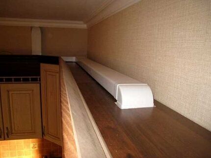
Correct selection of air duct parameters, taking into account all the features of the room, will ensure its long-term and efficient operation.
Calculation algorithm
When designing, adjusting or modifying an existing ventilation system, air duct calculations must be performed. This is necessary in order to correctly determine its parameters, taking into account the optimal performance and noise characteristics under current conditions.
When performing calculations, the results of measuring the flow rate and speed of air movement in the air channel are of great importance.
Air flow - the volume of air mass entering the ventilation system per unit of time. As a rule, this indicator is measured in m³/h.
Travel speed – a value that shows how quickly air moves in the ventilation system. This indicator is measured in m/s.
If these two indicators are known, the area of circular and rectangular sections, as well as the pressure required to overcome local resistance or friction, can be calculated.
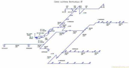
The most commonly used calculation algorithm is:
- Drawing up an axonometric diagram that lists all the elements.
- Based on this scheme, the length of each channel is calculated.
- Air flow is measured.
- The flow rate and pressure in each section of the system are determined.
- Friction losses are calculated.
- Using the required coefficient, the pressure loss when overcoming local resistance is calculated.
When performing calculations on each section of the network air distribution different results are obtained. All data must be equalized using diaphragms with the branch of the greatest resistance.
Calculation of cross-sectional area and diameter
Correct calculation of the area of round and rectangular sections is very important. An unsuitable cross-section size will not provide the desired air balance.
A duct that is too large will take up a lot of space and reduce the effective area of the room. If the channel size is too small, drafts will appear as the flow pressure increases.
In order to calculate the required cross-sectional area (S), you need to know the values of air flow and speed.
The following formula is used for calculations:
S = L/3600*V,
wherein L – air flow (m³/h), and V – its speed (m/s);
Using the following formula, you can calculate the diameter of the duct (D):
D = 1000*√(4*S/π), Where
S – cross-sectional area (m²);
π – 3,14.
If you plan to install rectangular rather than round air ducts, instead of the diameter, determine the required length/width of the air duct.
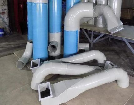
When choosing such an air duct, the approximate cross-section is taken into account. The principle used a*b ≈ S, Where a - length, b – width, and S - cross-sectional area.
According to the regulations, ratio width and length should not be higher than 1:3. You should also use the standard size chart provided by the manufacturer.
The most common sizes of rectangular ducts are: minimum dimensions - 0.1 m x 0.15 m, maximum - 2 m x 2 m. The advantage of round air ducts is that they have less resistance and, accordingly, create less noise during operation.
Calculation of pressure loss due to resistance
As air moves along the line, resistance is created.To overcome it, the fan of the air handling unit creates pressure, which is measured in Pascals (Pa).
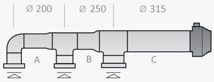
In order to select a suitableritochny installation with a fan of the required performance, it is necessary to calculate the pressure loss to overcome local resistance.
This formula applies:
P=R*L+Ei*V2*Y/2, Where
R – specific pressure loss due to friction in a certain section of the air duct;
L – length of the section (m);
Еi – total local loss coefficient;
V – air speed (m/s);
Y – air density (kg/m3).
Values R determined by standards. This indicator can also be calculated.
If the duct cross-section is circular, pressure loss due to friction (R) are calculated as follows:
R = (X*D/B) * (V*V*Y)/2g, Where
X – coefficient friction resistance;
L — length (m);
D – diameter (m);
V is the air speed (m/s), and Y is its density (kg/m³);
g - 9.8 m/s².
If the cross-section is not round, but rectangular, it is necessary to substitute an alternative diameter equal to D = 2AB/(A + B), where A and B are sides.
Calculation software
All calculations can be performed manually, but it is more convenient and faster to use specialized programs.
Using such programs, you can not only accurately perform the necessary calculations, but also prepare drawings.
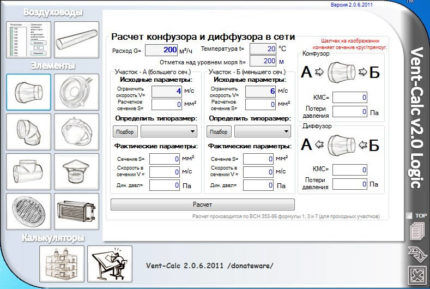
Vent—Calc – a functional application for calculating air ducts. For calculations, air flow and velocity values, as well as temperature, are used.
MagiCAD – performs all types of calculations for utility networks, images are presented in 2D and 3D formats.
GIDRV – a program for calculating all parameters of air ducts. It is possible to select any combination of parameters to achieve the best performance.
Ducter 2.5 – a utility that accurately calculates the diameters of air duct sections. Ideal for selecting their types.
The drawings that are drawn up in these programs allow you to more accurately see the layout of all system components and ensure their most efficient operation.
Measuring speed and air flow
When performing measurements, it is important to select the correct instruments and techniques, as well as to follow the procedures for performing measurements.
Instruments used for measurements
The most commonly used types of instrumentation are:
- ultrasonic 3D anemometer – performs measurements based on changes in sound frequency between specified points;
- Pitot tube – records the difference between static and total pressure;
- hot-wire anemometer – determines the flow rate based on the rate at which the sensor temperature decreases.
- winged anemometer - performs measurements based on changes in the speed of rotation of the impeller.
- bolometer – determines the air flow due to the concentration of the flow at the measurement point, the cross-section is pre-set.
Many of the devices on this list are quite expensive and rare.You can rent them and take measurements yourself, but it is better to call an experienced installation engineer who knows all the nuances of performing measurement work.
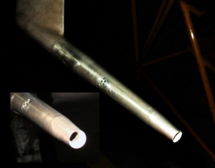
Velocity measurement is necessary not only for performing calculations, but also for monitoring the hygienic parameters of indoor air. Over a period of time it is inevitable that contamination of ventilation ducts and air ducts.
In such cases, connections may become depressurized and equipment performance will decrease. In addition, measurements are necessary for routine maintenance, cleaning and repair of the ventilation system.
When taking measurements, you must follow a number of rules. Firstly, air speed is regulated by building codes and standards. It is necessary to focus on these values.

Secondly, when taking measurements, it is also necessary to take into account the standards of associated factors - noise and vibration levels, which are specified in regulatory documents.
Exceeding these standards indicates shortcomings in the ventilation system. Air speed should not have any effect on these indicators.
Methods for performing air flow measurements
At the stage commissioning It is imperative to measure the volumetric air flow in the ventilation and air conditioning system.This will ensure the possibility of high-quality configuration of the system and its uninterrupted operation.
Such measurements are performed directly in the air duct or on the inlet grille. There are several simple techniques.
Measurements on ceiling diffusers
Most often, for measurements using this technique, it is used bolometer. Needs to be closed diffuser, and the top embarrassment attach to the ceiling. It is necessary to measure the total volume of air extracted from the room, and the supply flow.

Some sources recommend using a probe for measurements, inserting it into the gap between lamellas diffuser to obtain an average result.
This approach is ineffective for two reasons:
- The flow turbulence is very high, so the actual flow cannot be seen.
- It is not possible to align the probe directly with the flow. The measurement results will be distorted in any case.
Thus, you should not waste your time on unnecessary manipulations with the probe. There are much simpler and more accurate measurement methods.
There is another way to perform measurements using this technique. It provides for a straight section and uniform flow. Measurements are taken through pre-drilled holes.
This method is highly accurate, but there are not always conditions for its implementation. There are not straight sections everywhere; sometimes it is impossible to prepare two holes for measurements.Also, to implement this method you need several people: one must take measurements, the second must hold the stepladder, and so on.
Considering all of the above, if you need to get a quick and accurate result without making excessive efforts, use bolometer.
Measurements on the ventilation grille
To perform control and measurement operations using this technique, it is used hot-wire anemometer with an impeller from 60 to 100 mm in diameter. The impeller should be comparable to the dimensions of the grille.
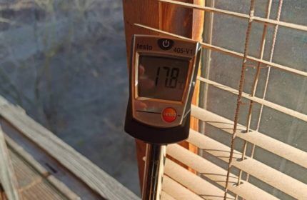
This method provides high accuracy of results, and the number of measurements performed is minimal. In order to provide access to hard-to-reach places, you can use a special extension or telescopic probe.
Duct measurements
To perform measurements, a specially made working hole in the wall of the air duct is used.
It is important to comply with the following conditions:
- the cross-sectional size of this hole must exactly correspond to the diameter of the probe;
- The location for measurements must be selected carefully. The hole is drilled only in a straight section, the length of which must be at least 5 diameters of the air duct. The hole must be positioned so that the distance before it is equal to 3 diameters, and after it - 2 pipe diameters.
When taking measurements inside an air duct, you need to use a device with an impeller with a diameter of 16 to 25 mm.If the air duct is located high, a telescopic probe or extension will come to the rescue.
Rules for using measuring devices
When measuring air flow speed and its consumption in a ventilation and air conditioning system, you need to correctly select devices and comply with the following rules for their operation.
This will allow you to obtain accurate results of air duct calculations, as well as create an objective picture ventilation systems.
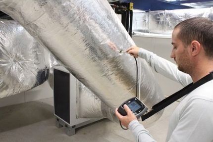
Observe the temperature regime indicated in the device passport. Also monitor the position of the probe sensor. It must always be oriented exactly towards the air flow.
If this rule is not followed, the measurement results will be distorted. The greater the deviation of the sensor from the ideal position, the higher the error will be.
Conclusions and useful video on the topic
Ventilation at home:
You can learn how to measure volumetric air on ventilation grilles in the following video:Thus, it is very important to follow the rules for performing measurements, because the slightest error can affect the calculation results.
Correct calculations of the air duct will allow you to select its optimal configuration and the necessary components, which means that the uninterrupted and productive functioning of ventilation will be ensured.
If you have any questions or can add valuable information to the material, please leave your comments and share your experience. The communication block is located under the article.


