Electrical diagram of a refrigerator: structure and principle of operation of various refrigerators
The refrigerator does not turn on and you need to find out the cause of the breakdown? Are you choosing a new unit and want to understand the differences in the operating principle of different models? The electrical diagram of the refrigerator, which reflects the interaction of its main components, will help with this.
By understanding the operating principle, you can avoid being deceived by technicians or repair the refrigerator yourself, as well as reduce the risk of breakdowns and increase the operating life of the device. In this article, we will look at diagrams of devices of various types: single-chamber and 2-3-chamber, with and without the NoFrost system, two-compressor, with mechanical and electronic control.
The content of the article:
Schematic diagram of the refrigerator
Just 30 - 40 years ago, household refrigerators had a fairly simple structure: the motor-compressor was started and turned off by 2 - 4 devices, and there was no question of using electronic control boards.
Modern models have many additional options, but the principle of operation remains generally unchanged.
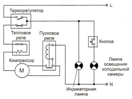
Thermostat – the main and only control element with which the user can configure the operation of an old refrigerator is usually located inside the refrigerator compartment. The bellows spring is hidden under the power lever - the rotating handle.It contracts when the chamber is cold, thereby opening the electrical circuit and turning off the compressor.
As soon as the temperature rises, the spring straightens and closes the circuit again. The refrigerator's freezing power indicator knob regulates the permissible temperature range: the maximum at which the compressor starts and the minimum at which cooling stops.
Thermal relay performs a protective function: it controls the temperature of the engine, therefore it is located directly next to it, often combined with a starting relay. If the permissible values are exceeded, and this can be 80 degrees or more, the bimetallic plate in the relay bends and breaks the contact.
The motor will not receive power until it cools down. This protects against both compressor failure due to overheating and a house fire.
Motor-compressor has 2 windings: working and starting. Voltage is supplied to the operating winding directly after all previous relays, but this is not enough to start. When the voltage on the operating winding increases, the starting relay is activated. It gives an impulse to the starting winding, and the rotor begins to rotate. As a result, the piston compresses and pushes through the system freon.
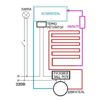
Generally refrigerator operating cycle can be described as follows:
- Connection to the network. The temperature in the chamber is high, the thermostat contacts are closed, the motor starts.
- Freon in the compressor is compressed, its temperature rises.
- The refrigerant is forced into the condenser coil, located behind or in the refrigerator tray.There it cools, gives off heat to the air and turns into a liquid state.
- Through the dryer, freon enters a thin capillary tube.
- Entering the evaporator located inside the refrigerator chamber, the refrigerant expands sharply due to an increase in the diameter of the tubes and the transition to a gaseous state. The resulting gas has a temperature below -15 degrees and absorbs heat from the refrigerator chambers.
- The slightly heated freon enters the compressor, and everything starts all over again.
- After some time, the temperature inside the refrigerator reaches the set values, the thermostat contacts open, the motor and freon movement stop.
- Under the influence of the temperature in the room, from new warm products in the chamber and opening the door, the temperature in the chamber rises, the thermostat closes the contacts and a new cooling cycle begins.
This diagram exactly describes the operation of old single-compartment refrigerators, which have one evaporator.
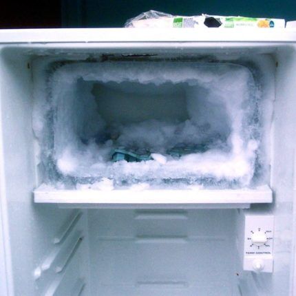
Typically, the evaporator is the freezer housing at the top of the unit, not isolated from the refrigeration chamber. We will consider the differences in the design of other models below.
Two-chamber and two-compressor models
In most available two-chamber models, there is a common freon circuit: after passing through the evaporator of the freezer, the refrigerant is directed into the main chamber, and only from there into compressor.
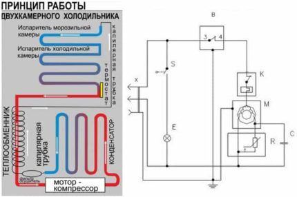
The motor is turned off by a signal from a thermal relay located in the main chamber; the general electrical circuit does not differ from single-chamber models.
IN refrigerators No Frost this system is often implemented with one common evaporator located in the partition between the chambers. The temperature difference is regulated by turbines and the number of air ducts; we’ll talk more about such models and their electrics later.
Dual-compressor models allow you to independently control the temperature in each chamber. Essentially, these are two separate, independent devices in one housing - accordingly, the electrical circuit is completely duplicated: a separate thermostat for each chamber, a separate start protection relay for each compressor.
Independent temperature control in each chamber is possible with one compressor, with a dual-circuit system. It can be implemented in various ways: with the advantage of freezing or completely independent circuits.
In the first case, the refrigerator thermostat closes the valve when the set temperature is reached, and the freon begins to circulate in a small circle - only through the freezer. The compressor stops when the freezer thermostat contacts open.
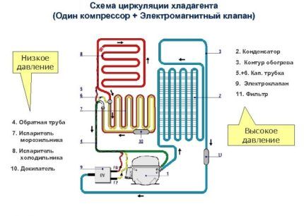
In the second option, freon has the ability to circulate through any one of the circuits or through both at once, and this process is regulated by opening and closing certain valves according to a signal from the electronic control board.
Three-chamber refrigerators and zero temperature zone
Fresh meat, poultry and fish are not stored for long in the main compartment of the refrigerator, and when frozen they lose some of their beneficial properties, taste and aroma. They are often provided with a separate box with a temperature close to zero, or even a separate chamber.
The temperature in the freshness zone is most accurately maintained under the following conditions:
- separate chamber with its own evaporator and thermistor, two- or three-circuit freon circulation system. The option is quite expensive and bulky, but the chamber volume is also significant;
- an insulated compartment in the main chamber of a refrigerator with a No Frost system, equipped with additional manually adjustable air ducts from the evaporator and a thermometer. Temperature accuracy depends on timely manual adjustment;
- a design similar to the previous one, in which the air dampers are controlled by an electronic unit.
An alternative option is cooling from the “crying” evaporator of the main chamber.

As you can see, the zero zone can be implemented in refrigerators with different electrical circuits; to ensure its operation, a thermostat or thermistor can be additionally included, and the electronic control board can also be expanded.
No Frost system and self-defrosting
The refrigerators described above have a drip defrosting system.This means that the refrigeration chamber is equipped with a “crying” evaporator: when the compressor is idle, the frost on it melts naturally, because the temperature in the chamber is positive.
The resulting water flows through special gutters through a tube into a container located above or near the motor. Later, the running motor becomes very hot and the water evaporates. A freezer with such a system never thaws on its own, and frost forms not only on the walls of the chamber, but also on the food.
No Frost refrigerators do not need to be defrosted; you will not see frost in their chambers, even in the freezer. A characteristic feature of such models is the presence of a fan that distributes cold air from the evaporator among the chambers.
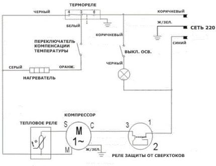
The cooling coil itself in such models does not look like the usual solid metal plate, but like a car radiator or the condenser coil on the back of old refrigerators.
In the general operation scheme of the refrigerator, the new elements behave as follows:
- the fan or turbine starts together with the compressor and evenly distributes cold air among the chambers;
- when the thermal relay opens the contacts supplying the engine due to the achievement of the set temperature, the fan is simultaneously turned off;
- Once every 8 - 16 hours the thermal relay turns on the heating element. This is an electrical mat or wire that heats the evaporator coil to remove frost from it. Warm air does not enter the refrigerator chambers, since the evaporator is hidden and the fan is turned off;
- when all the frost has thawed, the temperature compensation switch turns off the heating;
- Additionally, the thermostat can control a damper that regulates the supply of cold air into the main chamber through the channels.
Defrosting such refrigerators is similar to a “crying” evaporator in only one way: the resulting water also flows through the channels into a container near the motor.
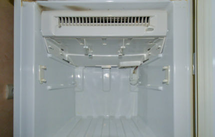
The scheme described above is the most primitive. Most modern models are controlled centrally, from an electronic board.
The main disadvantage of No Frost refrigerators is the drying out of food due to constant air circulation. Everything has to be stored in containers with tight lids or wrapped in film.
Original solution to the problem offers Electrolux V Frost Free system. In these units, the freezer operates according to the No Frost system, and a classic, “crying” evaporator is installed in the chamber with a positive temperature. The electrical circuit is generally identical to standard “no frost” systems.
Smart refrigerators with electronic control
Classic thermostats, with a mechanical rotary knob and a bellows inside, are becoming less and less common in modern refrigerators. They give way to electronic boards capable of managing an ever-increasing variety of operating modes and additional refrigerator options.
The function of determining the temperature instead of the bellows is performed by sensors - thermistors. They are much more accurate and compact, often installed not only in each refrigerator compartment, but also on the evaporator housing, in the ice maker and outside the refrigerator.
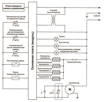
Control electronics of many refrigerators made on two boards. One can be called user: it is used to enter settings and display the current state. The second is system, through a microprocessor it controls all devices of the refrigerator to implement a given program.
A separate electronic module allows use in refrigerator inverter motor.
Such motors do not alternate cycles of operation at maximum power and idle time, like conventional ones, but only change the number of revolutions per minute, depending on the required power. As a result, the temperature in the refrigerator chambers is constant, electricity consumption is reduced, and the operating life of the compressor is increased.
The use of electronic control boards incredibly expands the functionality of refrigerators.
Modern models can be equipped with:
- control panel with or without display, with the ability to select and set the operating mode;
- multiple NTC temperature sensors;
- FAN fans;
- additional electric motors M - for example, for crushing ice in an ice generator;
- heaters HEATER for defrost systems, home bar, etc.;
- VALVE solenoid valves - for example, in a cooler;
- S/W switches for controlling the closing of the door and turning on additional devices;
- Wi-Fi adapter and remote control capability.
The electrical circuits of such devices are also repairable: even in the most complex system, the cause of a malfunction is often a faulty temperature sensor or similar small detail.

If the refrigerator “glitches” and refuses to correctly execute the specified program, or does not turn on at all, most likely the problem concerns the circuit board or the compressor; it is better to entrust the repair to a specialist.
Conclusions and useful video on the topic
How the compressor of a household refrigerator works and works is explained clearly and in detail in this video:
And here at the stand they assemble and connect all the elements of the electrical circuit of the No Frost refrigerator:
The entire variety of modern household refrigerators comes down to one basic electrical circuit, improved and supplemented with various components. No matter how different the latest Indesit model is from the old Minsk, they produce cold according to the same principle.
The electrical circuits of budget and old refrigerators are quite amenable to home repairs using a typical circuit, but the electronic control boards differ for each series. But even they have a similar general structure.
Which refrigerator did you prefer? Were you able to learn something new, interesting and useful from this article? Share your opinions, experiences and knowledge in the comments below.


This is not the first time I have come across this smart modern technology stuffed with electronic boards and microcircuits: microwave, oven, refrigerator, car (more fuss to take off). There is a lot of hassle with repairs. Mechanics are much simpler; even repairs can be performed without technical education or professional skills.