Gas and electric boilers in one system: features of assembling a parallel circuit
The classic heating scheme with one heat generator is well known to every home owner.However, by combining a gas and electric boiler in one system, a much greater practical effect can be achieved. They say that such a connection is much more economical than usual. Sounds tempting, doesn't it?
Logical reasoning raises doubts: how will electricity help save the budget, since its cost is much higher than gas? And why do this at all from the point of view of the feasibility of increasing the power of the units? Isn't it easier to just buy one productive boiler?
In fact, the project of such a combination is quite justified. We will tell you in detail how to assemble heating with electric and gas appliances. You will learn about the structure of this system and its feasibility. We will help you draw up a diagram and not miss the important nuances of arranging a combined heating line.
The content of the article:
Why install two boilers at once?
The role of the leader in the gas + electric combination is usually performed by a gas unit. This is logical, if only because of the lower cost of the fuel used in the supply. But the word “save” was mentioned above, and it is not clear what the cost reduction is.
The fact is that in many regions the electricity tariff is based on the day/night system. In some cases, it turns out, at least a little, but more economical than paying for gas. The difference is doubtful, but it can serve as an additional reason to add arguments for the double connective.
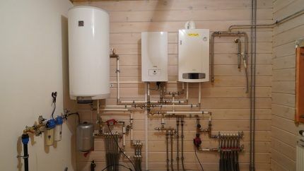
Of course, this is not such a compelling reason to immediately design a heating system with 2 boilers. The main advantages of the circuit are power amplification and uninterrupted operation. When choosing and installing a heat generator, you must clearly understand that any device and fuel supply are not eternal.
The power supply is turned off, the gas line may be blocked due to a leak, the voltage in the network will drop, or a simple breakdown of the unit itself will occur. In this case, you risk being left without heat and hot water during the cold season.
This is called connecting an additional (to enhance power) or backup power source, depending on the purposes and situations that arise.
Possibility of implementing joint connection
Designing a conventional gas-consuming heating system is not so easy. That is, it is easy to create a working scheme, but getting it approved is problematic. The situation with electric boilers less costly in terms of costs, time and problems with obtaining papers approving the procedure.
And here is the combination of 2 different fuel units. It would seem that you won’t run into problems and will have to go through the authorities for literally years to get permits. But that's not true.
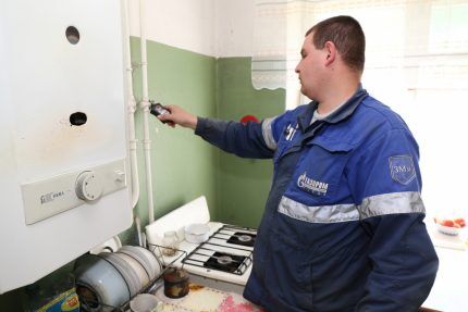
In fact, building regulations are quite favorable to such schemes. To be more precise, there are no prohibitions.
Energy and fuel consumption meters are different. Resource consumption is not exceeded, an explosive situation is not provoked - install boilers in compliance with standard standards and installation instructions for each. There shouldn't be any problems.
We remind you that the installation of gas boilers should be carried out in accordance with SP 402.1325800.2018 (and this document is mandatory and not advisory).
How to connect 2 boilers in the system?
You can’t just randomly connect 2 devices, the system will either not work or will work incorrectly. It is necessary to use carefully designed and competently designed ones from an engineering point of view.
There are two main connection schemes, these are:
- Sequential, when all elements are connected to each other without additional nodes. In this case, one device will heat the coolant, and the second will reheat it;
- Parallel, in which the devices included in the circuit have 2 connection points and the boilers operate independently of each other.
The sequential system is more suitable for low-power boiler installations and is rarely used.
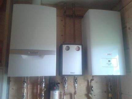
Meanwhile, parallel connection in a single system of gas and electric boilers has many advantages. Therefore, it is used most often, despite the fact that this arrangement requires more materials and is considered more expensive.
In such a device, you can turn off one of the devices at any time and even remove it for replacement or repair, while the second one will continue to operate as normal.
Features of parallel connection
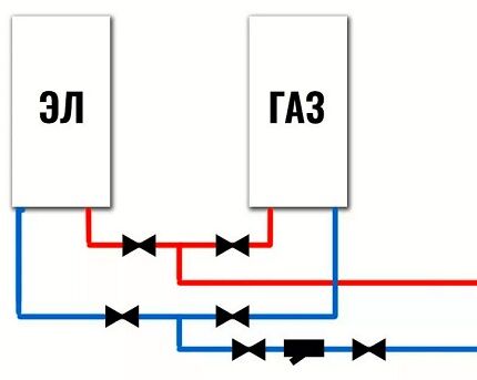
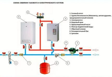
Let's take a closer look at what a standard parallel connection diagram for gas and electric boilers looks like:
- Each unit has coolant supply circuits. They join the common line.
- It is imperative that there are safety groups and shut-off valves.
- The return lines, also equipped with shut-off valves, are connected to the other line.
- On the return line (or on the supply line), in front of the unit for combining the piping contours, it is installed circulation pump.
- The lines of both heating units are connected to collectors.
- Installed on one of the distribution manifolds expansion tank. A make-up circuit is also connected to its pipe, equipped with a check valve and shut-off valves.
- From the distribution manifolds there are main branches to the heated floor, radiators, boiler, each with circulation pumps and valves for draining the coolant from the system.
This is not a schematic diagram, but only its main features.It gives a general idea of how best to connect an additional electric boiler to the main gas boiler. The assembly option can be complicated and improved, for example, with an automation system and a servo drive.
Manual/automatic control options
Control of the boiler backup system or shutdown of failed ones can be carried out manually or automatically. It is not advisable to leave the system running with one boiler turned off, since the water will continue to circulate.
Imagine what will happen when the cooled return flows in the opposite direction and begins to mix with the supply, cooling the coolant and causing the pump to work in vain.
If for some reason you do not want to equip the boilers with complex devices, you will start the unit yourself. That is, everything is standard: you need to turn on the device - turn all the necessary valves and turn it on. When disconnecting, perform the steps in reverse order.
If you want the backup equipment to start automatically, the system is equipped with automatic thermostats, indoor and outdoor air temperature sensors, coolant temperature sensors, servos.
In the circuit diagram of the automatic backup start of the heating unit, all shut-off valves must be in the open position. According to the counter scheme, the system is equipped check valvesto avoid parasitic circulation of coolant through a boiler that is not operating at a certain time.
However, despite the convenience, the system can cause certain problems, for example, hydraulic resistance of check valves, causing stress on the pumps, contamination and wear of the devices themselves.
To automatically turn on the heating boiler, the system is equipped with a thermostat, which sends commands to the control unit, depending on the temperature in the house. The switch-on time for night standby use is set on a timer. Circulation pump switched off using a magnetic starter.
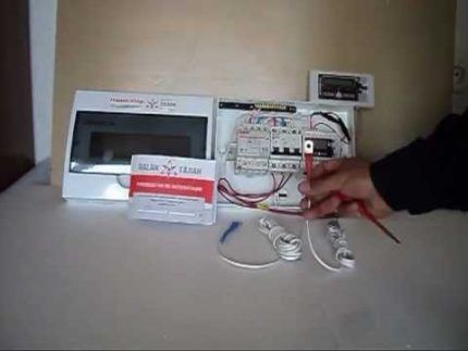
When choosing a control that will be equipped with an electric boiler installed in parallel with a gas boiler, you should opt for automation if:
- The backup boiler is turned on at night, when it is inconvenient to start it manually.
- In case of long trips from home during the heating season.
- If the gas boiler is unreliable.
In other cases, it is quite possible to use the simplest manual scheme.
Hydraulic arrow in a parallel connection system
A hydraulic arrow is a device that provides hydraulic isolation of flows supplied to individual circuits of the heating system. It plays the role of a buffer tank, receiving the flow of coolant heated by the boilers and distributing it to consumers in a branched system.
Often the volume of coolant required for them differs, the speed of movement of the heated water and its pressure differ. And in the situation under consideration, the movement of heated water from each of the boilers also stimulates its own circulation pump.
When the powerful pump is turned on, the coolant is unevenly distributed throughout the circuits. So here's the task hydraulic guns is to equalize this pressure. Due to the fact that there is virtually no hydraulic resistance inside it, it will freely receive and distribute coolant flows from both boilers.
Let’s figure out whether it is really necessary in a parallel system for connecting 2 boilers, especially since if you buy and install a hydraulic separator with the help of a specialist, and not with your own hands, the total amount will be unpleasantly surprising.
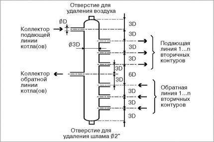
In the classic connection scheme, a hydraulic separator is usually not required, since the conflict of 2-3 pumps can be equalized without this device. Accordingly, if you have 2 boilers that are used exclusively as a backup and there are no more than 3-4 pumps in the system, there is no particular need for it.
But if the contours with forced circulation more or heating boilers work simultaneously at power - it is best to install this device.Again, it is unknown whether you will use the second boiler permanently or only in backup mode, so it is better to be safe.
Conclusions and useful video on the topic
Synchronization of operation and shutdown of boilers in a parallel installation:
Installing 2 heating boilers, gas and electric, is a wise solution to increase the power of heating equipment, as well as for backup heating of the building. Parallel installation of units is not as difficult as it might seem at first.
The main thing is to correctly select the arrangement scheme and correctly calculate the total or reserve power of the equipment. If you are not confident in your abilities and cannot cope on your own, it is best to contact plumbers. They will help you quickly and efficiently install a system for reliable and comfortable heating of your home.


Where can I get such a master?