SF6 circuit breakers: guidelines for selection and connection rules
The functioning of high-voltage electrical networks in terms of current characteristics is not comparable with the operation of household analogues.Accordingly, in the event of an emergency, more powerful devices than standard automatic devices are needed to turn off the equipment and extinguish the electric arc.
SF6 circuit breakers (EGS) are used as protective structures, which can be controlled both manually and automatically. We have described in detail the design features and operating principle of the devices. Provided recommendations for installation, connection and maintenance.
The content of the article:
Definition and Application of SF6 Gas
SF6 gas is sulfur hexafluoride, which is classified as an electrical gas. Due to its insulating properties, it is actively used in the production of electrical devices.
In its neutral state, SF6 gas is a non-flammable, colorless and odorless gas. If we compare it with air, we can note its high density (6.7) and molecular weight, which is 5 times higher than air.
One of the advantages of SF6 gas is its resistance to external manifestations. It does not change characteristics under any conditions. If disintegration occurs during an electric discharge, then a full restoration necessary for operation soon occurs.
The secret is that SF6 molecules bind electrons and form negative ions. The quality of “electronegation” endowed 6-sulfur fluoride with such a characteristic as electrical strength.
In practice, the electrical strength of air is 2-3 times weaker than the same property of SF6 gas.Among other things, it is fireproof, as it is a non-flammable substance, and has cooling properties.

The listed characteristics made SF6 gas most suitable for use in the electrical field, in particular in the following devices:
- power transformers operating on the principle of magnetic induction;
- complete type switchgears;
- high voltage lines connecting remote installations;
- high voltage switches.
But some properties of SF6 gas led to the need to improve the design of the switch. The main disadvantage concerns the transition of the gaseous phase to the liquid phase, and this is possible under certain ratios of pressure and temperature parameters.
In order for the equipment to operate without interruption, it is necessary to provide comfortable conditions. Let’s assume that for the operation of SF6 devices at -40º, a pressure of no more than 0.4 MPa and a density of less than 0.03 g/cm³ are required. In practice, if necessary, the gas is heated, which prevents the transition to the liquid phase.
SF6 circuit breaker design
If we compare SF6 devices with analogues of other types, then in design they are closest to oil devices. The difference lies in the filling of the chambers to extinguish the arc.
As a filler oil switches an oil mixture is used, while SF6 ones use 6-sulfur fluoride. The advantage of the second option is durability and minimal maintenance.
Methods for extinguishing an electric arc depend on many factors, among which the rated current and voltage, as well as the conditions of use of the device, are decisive.
There are four types of EVs in total:
- with electromagnetic blast;
- with SF6 gas blast – with 1 pressure stage;
- with longitudinal blast – with 2 pressure levels;
- with self-generating blast.
If in air devices the gas enters the atmosphere during the arc extinguishing process, then in SF6 devices it remains in a closed space filled with a gas mixture. At the same time, a slight excess pressure remains.
Column and tank devices
In practice, two types of SF6 gas plants are used:
- tank;
- core.
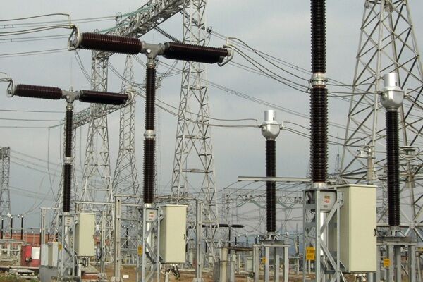
The differences relate to both design features and the principle of extinguishing the electric arc. In terms of their external structure, core rods resemble low-oil analogues: they consist of two functional parts - arc extinguishing and contact, and have the same volumetric dimensions.
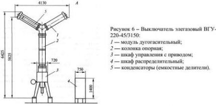
Disconnecting devices are designed to operate from a 220 V network and belong to single-phase equipment. An example of a column-type SF6 gas switch is the LF 10 Schneider Electric.

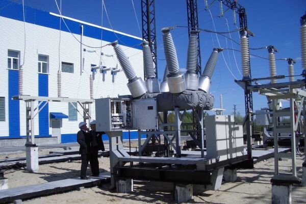
Tank-based SF6 appliances are smaller in size and are equipped with a multi-phase drive. This distribution allows for better control and smooth adjustment of voltage parameters.

An example of a tank device is the DT2-550 F3 Alstom Grid gas installation. Such devices have proven themselves in electrical systems with a voltage of 500 kV.
The structure is assembled and equipped in such a way that it functions without failure at low temperatures (critical), high humidity, as well as in regions with seismic activity and excessive atmospheric pollution.
Arc extinction principle
Let's look at how the device works using the example of the LW36 switch from the Chinese manufacturer CHINT.
When disconnected, the spring acts on the dynamic elements of the cylinder, and they fall down. All contacts, except arc extinguishing contacts, open. When the arcing contacts carrying current are disconnected, an electric arc occurs.
Hot gas moves into the thermal chamber, and the check valve is activated. When gas from the heat chamber is blown into the gap, the arc is extinguished.
If small currents are switched off, then the pressure in the thermal chamber is not enough, so pressure from the compression chamber is attracted (it is always higher). The check valve opens, gas flows freely into the gap and, when crossing zero, extinguishes the arc.

Modern core installations have improved characteristics. Maintenance is reduced to a minimum, switching life is increased. SF6 circuit breakers are characterized by low noise levels, reliable mechanics, and ease of installation and testing.
Tank models are adjusted using a drive and transformers. A spring or spring-hydraulic drive controls the on/off processes and the level of arc retention.
What is the drive for?
The drive is designed to perform all operations related to turning on/off or holding the installation in a certain position. The diagram shows exactly where the drive can be located. This is usually the ground surface or a low support that provides maintenance personnel with easy access to control devices.

The drive consists of an activation mechanism, a locking device - a latch, and a release mechanism. The switching process should occur as quickly as possible to avoid welding of contacts.
During switching on, great efforts are made to overcome the frictional force of all involved elements. Disabling is simpler and involves the reverse movement of the latch, which ensures activation and retention.
There are several ways to enable/disable:
- mechanical;
- spring;
- cargo;
- pneumatic;
- electromagnetic.
For low-power systems, manual control is used. In this case, the strength of one operator is sufficient. Manual mechanisms are usually switched off automatically. The spring drive is also manually actuated, but sometimes low-power electric motors are used.

Magnetic actuator operation requires more power and requires a constant current source of approximately 58 A at 220 V. A manual lever is provided as a backup trip mechanism. Electromagnetic devices They are reliable, so they are successfully used in areas with harsh winters. The downside is the need for a powerful battery.
The pneumatic drive differs in that instead of an electromagnet, the main working element is a cylinder/piston pair. Thanks to compressed air, the activation speed is much faster than previous models.
Advantages and disadvantages of using EVs
SF6 circuit breakers, like other types of electrical distribution devices, have a number of advantages and disadvantages. When choosing an installation, the necessary calculations are made and, in addition to technical characteristics and design features, the pros and cons of the models are taken into account.
SF6 type switches operate in difficult conditions with periodic vibrations, low temperatures (with heating), and in fire hazardous areas.
The disadvantages include the high cost of the filler - SF6, the specifics of installation on a panel or foundation, and the need for certain qualifications of the operator staff.
Rules for connecting and servicing EVs
All actions related to installation, switching on/off, repair and maintenance of SF6 devices are subject to strict rules that are regulated by PUE 1.8.21.
To connect the installation, it is necessary to check the presence of minimum pressure in the gas-filled chamber, otherwise the switch will fail. To prevent damage, an alarm is installed that is triggered when pressure parameters drop critically. The pressure level can be monitored using a pressure gauge.
The drive cabinet is equipped with heating elements that effectively prevent the formation of condensation on the mechanism elements. The operator must ensure that the heaters are always on.

During the inspection of the circuit breaker, it is necessary to check the external protection, remove dirt, and correct damage. If the contacts heat up, you should find out the reason.
If there is a crackling or suspicious noise, you need to identify the source. The metal mounting structure is also part of ground loop, therefore its integrity should be checked.
The pressure gauge readings must be taken. The pressure must correspond to the norm calculated by the manufacturer.It is necessary to check the serviceability of regulating and monitoring devices, and if one or more elements fail, take action - replace it or send it for repair.
If the gas pressure has decreased, the chamber should be refilled with SF6 gas. The insulation does not need to be cleaned, since the structure is completely sealed.
Conclusions and useful video on the topic
You can learn how SF6 switches are designed, on what principle the arc is extinguished, and what types of devices there are from a useful and informative video.
Video #1. Review of SF6 switches with a description of the device and operating principle:
Video #2. Features of the installation design:
Video #3. How to install the switch:
SF6 circuit breakers leave the factory assembly line in full operational readiness and are designed to operate in a variety of climatic zones, from tropical to cold, and therefore are actively used by industrial companies in various countries.


