Oil switch: types, markings + specifics of use
Among the switching equipment, the oil circuit breaker, used in both closed and open switchgears of any voltage, occupies a place of honor as a veteran.
Its main function is to turn on and off individual lines of a normally operating electrical system or in unusual situations. Depending on the circumstances, shutdown occurs automatically or manually.
In this article we will look at the existing types of these devices, their classification and labeling. We will also pay attention to the pros and cons of such switches, features and rules for their use. For a better understanding of the material, we have selected diagrams, tables, visual photos and thematic video reviews.
The content of the article:
Pros and cons of oil switches
These devices have a relatively simple design. They have good switching capacity and are not affected by weather conditions. If malfunctions occur, repair work can be carried out. Tank MVs are suitable for outdoor installation. There are conditions for the installation of built-in current transformers.
The speed of contact divergence plays an important role in the operation of the MV. A situation may arise when the contacts diverge at enormous speed and the arc instantly reaches a length that is critical for it. In this case, the magnitude of the recovering voltage may not be enough to break through the intercontact gap.
Tank switches have more disadvantages.The first is the presence of a large volume of oil, therefore, the considerable dimensions of these units and switchgear. The second is fire and explosion hazard; in emergency situations, the consequences can be the most unpredictable.
The oil level both in the tank and in the inlets, as well as its condition, must be kept under periodic monitoring. If there is a MV in the serviced power supply networks, it is necessary to have a special oil facility.
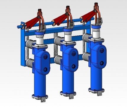
Classification of oil switches
The use of oil switches began at the end of the century before last. Almost until the middle of the twentieth century, there were simply no other disconnecting devices in high-voltage networks.
There are two large groups of these devices:
- Tank, which are characterized by the presence of a large volume of oil. For this equipment, it is both the medium in which the arc is extinguished and the insulation.
- Low oil or low volume. The name itself speaks about the amount of filler in them. These switches contain dielectric elements and require oil only for arc extinguishing.
The former are used mainly in distribution installations from 35 to 220 kV. The second - up to 10 kV. Low-oil devices of the VMT series are also used in outdoor switchgears designed for 110 and 220 kV.
The principle of arc extinguishing is identical for both types. The arc that appears when the high-voltage contacts of the switch are opened causes rapid evaporation of the oil. This leads to the creation of a gas shell around the arc. This formation consists of oil vapor (about 20%) and hydrogen (H2).
The arc gap is deionized as a result of rapid cooling of the arc barrel by mixing high and low temperature gases in the shell.
At the moment of arcing in the contact zone, the temperature is very high - about 6000⁰. Depending on the installation, there are switches used for internal, external use, as well as for use in KRP - complete switchgears.
Type #1 - tank-type equipment
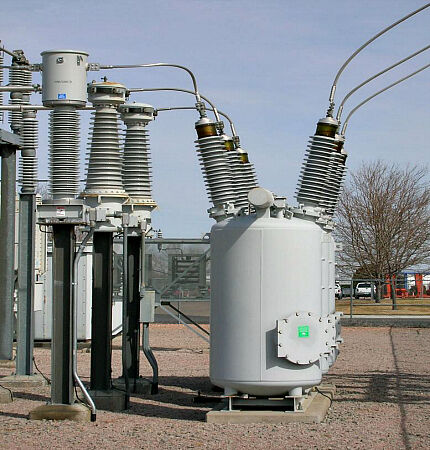
Switching equipment of this type may have one tank or more depending on the voltage. In the first case, this is up to 10 kV, in some cases up to 35. Each phase of switches operating in high-voltage installations is placed in an individual tank.
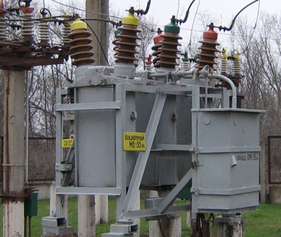
Drives to both tank and low-oil switches can be manual, automatic, assembled on a solenoid actuating coil, or spring-loaded. In the second case, the magnetic property of the solenoid is used, which allows it to tighten the metal core connected through a special system to the MV shaft.
When electric direct current is supplied to the solenoid winding, the unit is turned on by retracting the magnetic core rod and then rotating the switch shaft.
A special latch holds the shaft in this position. Simultaneously with turning on, the solenoid sets a certain position to the shutdown springs, which, upon receipt of a special electrical impulse, will turn off the MV.
The shutdown process initiates the second solenoid by knocking out the roller mechanism (latch).As a result, the shaft instantly rotates due to the spring and switches off. For the solenoid drive to operate, a battery must be present to power it with direct current.
When there is no battery, a spring drive is used. Switching is performed using an electric motor or through muscular effort. Manual shutdown is possible for low-power units with a short-circuit current value of up to 30 kA, to turn them off you need to apply a maximum force of 25 kg.
Single-tank MV with open arc
Some switchgears are equipped with tank circuit breakers that do not have arc chutes. The electric arc here is extinguished in the simplest way - by breaking the contacts in an oil-filled container twice. Such devices with an open arc include domestic models VMB and VME. They are designed for a rated current of 1.25 kA.
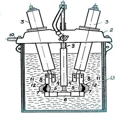
The symbol “E” stands for excavator, the number 6 is the rated voltage of 6 kV, 200 is the rated current in amperes. The threshold shutdown current for this MV is 1.25 kA. The tank of this MV is made of steel and connected to a cast iron lid using bolts. The walls of the tank are covered with insulation (13).
Six porcelain insulators passing through the lid end in copper brackets that serve as fixed working contacts. The VME series has a manual flywheel drive.
There are movable contacts on the traverse or contact bridge. Arc-extinguishing mobile contacts in the form of brass squares are also located here.Copper plates with brass tips located at the bottom ends of the insulators are stationary arcing contacts. An insulating rod communicates movement to the moving contacts through contact with the drive mechanism.
When the traverse is in the raised position, the fixed contacts are closed, the spring responsible for shutdown is compressed, and the MV is turned on. The switch is connected to a latch drive shaft, which holds it in the operating position. Whenever it is disconnected, the latch is released, the spring is released, and the traverse quickly moves downwards. In this case, the working contacts are opened sequentially: 4 and 5, then 7,8.
This causes each pole of the switch to open the circuit at two points, arcing, and decomposing the oil. Inside the shells 12, the pressure reaches from 0.5 to 1 MPa, thereby activating the deionization process. Within a maximum of 0.1 s, the arcs are extinguished, and the shells, rising, end up under the cover and increase the volume of the air cushion.
The latter acts as a buffer, reducing the impact force during the arc extinguishing process. The normal height of the air cushion is approximately 25% of the volume. Exceeding this threshold may result in an explosion.
Such switches are easy to operate, relatively inexpensive, and convenient to use in open substations. But hot oil vapors, even in simple contact with oxygen, are easily flammable.
Burning an arc in an oil environment triggers the process of polycondensation, which deteriorates the electrical strength of the oil. The tank becomes clogged with sediment consisting of carbon particles. Therefore, inspections of the unit with an oil change are necessary.
Oil switches with arc chute
The breaking capacity and reliability of tank-type circuit breakers is significantly increased by the presence of an arc chute. It is placed in the oil located in the tank. In three-tank circuit breakers, each phase is placed in a separate tank.
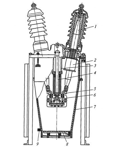
The design is more complex than that of a VM without arc chutes and consists of:
- poles (1);
- current transformer (2);
- drive housing (3);
- rods (4);
- fixed contact (5);
- arc extinguishing chamber (6);
- insulation (7);
- heating element (8);
- oil drain devices (9).
The top of the camera is equipped with a fixed contact. When turned on, a moving contact shaped like a rod penetrates into it. In the event of a disconnection, the rod leaves the fixed contact, resulting in an arc appearing in the chamber. The amount of pressure generated in this case is an order of magnitude higher than the corresponding parameter of switches that are not equipped with an arc chute.
A pressure of 8 -7 MPa reduces the diameter of the arc and increases the breakdown strength of the gap after the current passes through the zero mark. As a result, a faster arc extinguishing process occurs. Following the exit of the moving contact from the chamber, gases are released through the free hole with partial capture of oil.
The arc barrel cools quickly and intense deionization occurs. As the current increases, the efficiency of the arc chute increases.The MV can also operate as open-arc equipment in the event of a small current interruption.
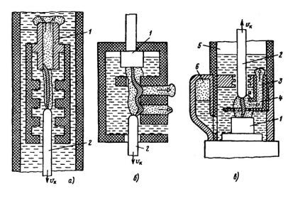
The type of automatic blowing is determined by the design of the arc chute. In the first case, the vector of the vapor mixture has a longitudinal direction with respect to the arc shaft (fragment a). With a transverse direction of blowing, the flow moves in a direction perpendicular to the arc column or at a certain angle (fragment b).
In the case when the flow has a direction opposite to the vector of movement of the mobile contact with the arc, counter blowing occurs. Combinations of these methods are often used in arc extinguishing devices.
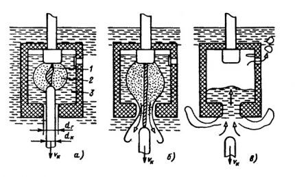
At the last stage, the chamber is prepared to participate in the next shutdown cycle. For automatic re-shutdown, this step is extremely important.
Type #2 - pot or low oil switches
In closed installations, pot circuit breakers are used as generators and distribution circuits. In open ones - as substation and distribution. Oil does not perform insulating functions in switches of this type; it is necessary only as a medium for extinguishing the arc.
The fire and explosion hazard of small-volume VMs is significantly lower than that of tank-based ones.They are installed both in outdoor switchgear and indoor switchgear of any voltage up to 110 kV. The role of insulating the poles in relation to each other and the ground is performed by dielectrics such as porcelain, cast resin, steatite.
The oil in these VMs occupies only 3 to 4% of the pole volume. A small volume of oil, low weight and convenient dimensions are the undeniable advantages of this equipment. However, they are used in such system components where high demands are not placed on switches.
These limitations are explained by the strong connection between the disconnecting capacity and the interrupted current, and the inability of the design to operate under conditions of frequent outages.
Another reason is the difficulty in implementing multiple high-speed automatic reclosures. In small-volume switches, the following types of oil blast are used: transverse, longitudinal, mixed. Experts consider the first one to be the most effective.
For switches of this type, intended for closed switchgear, the contacts are placed in a steel tank. MVs with voltages of 35 kV and higher have a porcelain shell. The most commonly used equipment is suspended 6-10 kV. Its body is fixed on a frame common to all poles. All three poles have an arc-extinguishing chamber, each is designed for one contact break, and at high voltages for 2 or more.
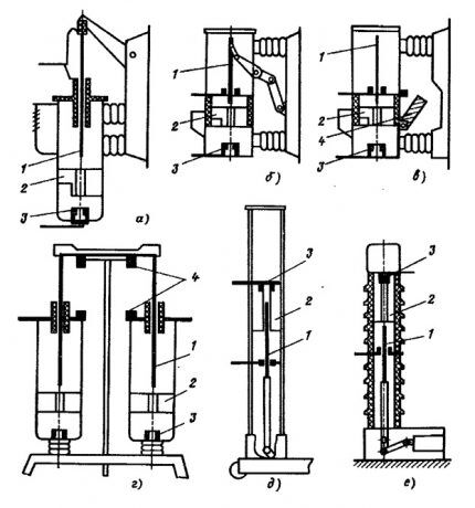
According to the above diagram, VMP, VMG, MG switches are produced, designed for voltages up to 20 kV. A design feature of switches for high current ratings is that the working contacts are located outside, and the arc extinguishing contacts are located inside the tank.
VMP series circuit breakers are often used in closed devices, as well as 6-10 kV switchgear. Switchgears of the VK series are installed in complete switchgears. They are equipped with a built-in electromagnetic or spring drive, and are designed for breaking currents of 20 - 31.5 kA and current ratings of 630 - 3150 A.
Column switches, manufactured specifically for switchgear, are distinguished by their retractable design. In 35 kV installations, column-type VMs of the VMK and VMUE series are installed. RU 110, 220 kV are equipped with circuit breakers of the VMT series. The unit has a welded base on which its three poles are located. Control - spring drive.
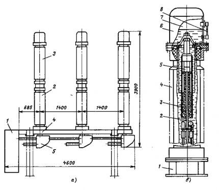
The right side of the photo shows a module, where: 1 is a down conductor, 2 is a moving contact connected to the down conductor through current collectors. The arcing chamber is designated by number 3, the fixed contact is 5. All of the above is placed in a hollow insulator (4) made of porcelain. Inside it is transformer oil, and on top is a cap (6).
The latter is equipped with a pressure gauge to monitor the pressure in the module. In addition, the cover has a unit for filling with a compressed gas mixture, an automatic release valve, and an oil indicator (8). The mobile contact and the control device are connected by insulating rods.
The design of the pole is identical for the entire series of switches. MV tanks for current ratings from 630 to 1600 A contain 5.5 kg of oil, above 1600 and up to 3150 A inclusive - 8 kg.
To increase reliability, the design of individual switches includes additional control and protection elements:
- disconnecting electromagnets;
- relays operating instantly and with a delay at a threshold current;
- minimum voltage relay;
- additional contacts.
Depending on the layout method, there are low-oil circuit breakers with the arc chute located at the bottom and the opposite at the top. In the first case, the moving contact implements movement from top to bottom, in the second - vice versa. The breaking capacity of the latter is higher.
Marking of oil switches
Deciphering the markings applied by the manufacturer to the oil switch will allow you to familiarize yourself with basic information about it. Let us look at the markings of the VMG-133 switch as an example. The first character “B” indicates that there is a switch in front of you.
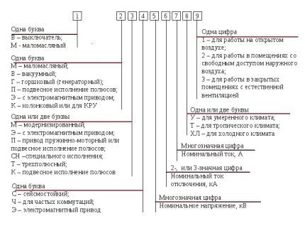
Second - "M" denotes the type of switch, in this particular case - low-oil. Letter "G" determines belonging to a certain species - potted. 133 - MV series.
Rules for operating the MV
Repair and operational personnel, specialists associated with the maintenance and operation of oil switches are required to know the relevant instructions, structure, and operating principle of the equipment.
During operation, workers servicing the MV are required to monitor:
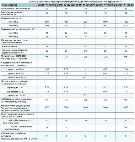
- Effective voltage, load current. Indicators should not go beyond the table values.
- The height of the oil column at the poles, the absence of leaks.
- Presence of lubricant on rubbing parts.Contacts may lose mobility and freeze if the lubricant of the rubbing elements becomes thick and dirty.
- Dust in the rooms where switchgear is located.
- Compliance of the mechanical characteristics of the operated switches with the tabular standards.
After each short circuit trip, the equipment must be inspected. Information about these outages is recorded in a special log. There must be a defect log to record information about malfunctions identified during operation of the unit. The switch on which the shutdown occurred as a result of a short circuit is subject to inspection.
Check for oil leakage. If this happens, and in large quantities, then this indicates an abnormal shutdown of the short circuit. The equipment is taken out of service and inspected. When the oil is dark, it needs to be changed. The opening speed is negatively affected by the viscosity of the oil, which increases as the temperature drops.
Sometimes it becomes necessary to replace the old lubricant with a new one during repairs: CIATIM-221, GOI-54 or CIATIM-201.
After the MV is removed from operation, the support insulators, rods, and tank insulation are subject to thorough inspection for the presence of cracks. Heavily contaminated insulation is wiped. The need for emergency repairs appears after a certain number of short circuits.
Periodic inspection (PI) is performed monthly. In this case, pay attention to the degree of heating of the switch. TR (current repairs) are carried out annually. It includes work such as checking and eliminating defects in fasteners, drive kinematics, oil level, and seals.The insulating parts are also checked for their integrity.
After 3-4 years after major repairs, a medium repair (SR) is performed. It includes the entire set of TR works, plus they additionally measure the contact resistance of the poles and check the mechanical and speed parameters.
If a discrepancy between the monitored characteristics and tabular data is detected, the switch is disassembled, adjustments and a full range of high-voltage tests are performed.
During extraordinary repairs, they generally try to leave the previous adjustment unchanged. For this reason, the switch is disassembled to a minimum. The frequency of major repairs is from 6 to 8 years. In its scope, a general inspection is performed, the cylinders are removed from the frame, the tires are disconnected, the drive, arc extinguishing devices, and block contacts are repaired.
After everything, adjustments are made, painting is done, tires are connected, and tests are carried out. Documentation is drawn up for all work.
In addition to oil-type switches, other disconnecting devices are also used in high-voltage networks. For example, SF6 and vacuum. We have other articles on our website that discuss in detail the characteristics and design of these types of switches, as well as the features of their use:
- Vacuum switch: device and principle of operation + nuances of selection and connection
- SF6 circuit breakers: guidelines for selection and connection rules
Conclusions and useful video on the topic
Design, types, purpose and operation of MV:
Detailed review of VMP-10:
Oil switches also meet all the basic requirements for circuit breakers operating in high voltage conditions.Most of them are safe and reliable in operation, provide quick shutdown, and are easy to install. Despite this, manufacturers are striving to ensure even greater compliance with the requirements put forward for MV.
Do you have knowledge about oil switches and want to supplement the presented material with useful information? Perhaps you noticed a discrepancy or error? Or do you still have questions on the topic? Please write to us about this under the article - we will be grateful to you.


Please tell me what is the difference between VMP and VPM oil switches?
The scope of application of VPM (and its predecessor VMG) is in internal installations, and VMP is in closed switchgears, as well as 6-10 kV switchgear.
To make it more clear, I’ll explain a little more. Using the example of VMP-10 and VPM-10. Both switches are of the low-oil type and are implemented in the form of three-pole switching devices. VMP-10 and VPM-10 are designed for operation in closed installations with high voltage alternating current. The difference lies in the design features and installation methods. Attaching photo.