Do-it-yourself powerful voltage stabilizer: circuit diagrams + step-by-step assembly instructions
Making homemade voltage stabilizers is a fairly common practice.However, for the most part, stabilizing electronic circuits are created that are designed for relatively low output voltages (5-36 volts) and relatively low powers. The devices are used as part of household equipment, nothing more.
We will tell you how to make a powerful voltage stabilizer with your own hands. The article we have proposed describes the process of manufacturing a device for working with a network voltage of 220 volts. Taking into account our advice, you can handle the assembly yourself without any problems.
The content of the article:
Stabilization of household voltage
The desire to provide stabilized voltage to the household network is an obvious phenomenon. This approach ensures the safety of the equipment in use, often expensive and constantly needed on the farm. And in general, the stabilization factor is the key to increased safety in the operation of electrical networks.
Most often purchased for household purposes stabilizer for gas boiler, the automation of which requires connection to a power supply, for refrigerator, pumping equipment, split systems and similar consumers.

This problem can be solved in different ways, the simplest of which is to buy a powerful voltage stabilizer manufactured industrially.
Offers voltage stabilizers there are plenty on the commercial market. However, purchasing options are often limited by the cost of devices or other factors. Accordingly, an alternative to purchasing is to assemble a voltage stabilizer yourself from available electronic components.
Provided you have the appropriate skills and knowledge of electrical installation, the theory of electrical engineering (electronics), wiring circuits and soldering elements, a homemade voltage stabilizer can be implemented and successfully used in practice. There are such examples.

Circuit solutions for stabilizing the 220V power grid
When considering possible circuit solutions for voltage stabilization, taking into account relatively high power (at least 1-2 kW), one should keep in mind the variety of technologies.
There are several circuit solutions that determine the technological capabilities of devices:
- ferroresonant;
- servo-driven;
- electronic;
- inverter
Which option to choose depends on your preferences, available materials for assembly and skills in working with electrical equipment.
Option #1 - ferroresonant circuit
For self-production, the simplest circuit option seems to be the first item on the list - a ferroresonant circuit. It works using the magnetic resonance effect.

The design of a sufficiently powerful ferroresonant stabilizer can be assembled using only three elements:
- Throttle 1.
- Throttle 2.
- Capacitor.
However, the simplicity in this option is accompanied by a lot of inconveniences. The design of a powerful stabilizer, assembled using a ferroresonant circuit, turns out to be massive, bulky, and heavy.
Option #2 - autotransformer or servo drive
In fact, we are talking about a circuit that uses the principle of an autotransformer. Voltage transformation is automatically carried out by controlling a rheostat, the slider of which moves the servo drive.
In turn, the servo drive is controlled by a signal received, for example, from a voltage level sensor.

A relay-type device operates in approximately the same way, with the only difference being that the transformation ratio changes, if necessary, by connecting or disconnecting the corresponding windings using a relay.
Circuits of this kind look technically more complex, but at the same time they do not provide sufficient linearity of voltage changes. It is permissible to assemble a relay or servo-drive device manually.However, it is wiser to choose the electronic option. The costs of effort and money are almost the same.
Option #3 - electronic circuit
Assembling a powerful stabilizer using an electronic control circuit with an extensive range of radio components on sale becomes quite possible. As a rule, such circuits are assembled on electronic components - triacs (thyristors, transistors).
A number of voltage stabilizer circuits have also been developed, where power field-effect transistors are used as switches.
It is quite difficult to manufacture a powerful device completely under electronic control with the hands of a non-specialist; it is better buy a ready-made device. In this matter, you cannot do without experience and knowledge in the field of electrical engineering.
It is advisable to consider this option for independent production if there is a strong desire to build a stabilizer, plus the accumulated experience of an electronics engineer. Further in the article we will look at the design of an electronic design suitable for making it yourself.
Detailed Assembly Instructions
The circuit being considered for self-production is rather a hybrid option, since it involves the use of a power transformer in conjunction with electronics. The transformer in this case is used from among those that were installed in televisions of older models.

True, TV receivers, as a rule, installed TS-180 transformers, while the stabilizer requires at least a TS-320 to provide an output load of up to 2 kW.
Step #1 - making the stabilizer body
To make the device body, any suitable box based on an insulating material - plastic, textolite, etc. is suitable. The main criterion is sufficient space for placing a power transformer, electronic board and other components.
It is also possible to make the body from fiberglass sheets by fastening individual sheets using corners or in another way.

The stabilizer box must be equipped with grooves for installing a switch, input and output interfaces, as well as other accessories provided by the circuit as control or switching elements.
Under the manufactured case, you need a base plate on which the electronic board will “lie” and the transformer will be fixed. The plate can be made of aluminum, but insulators should be provided for mounting the electronic board.
Step #2 - making a printed circuit board
Here you will need to initially design a layout for the placement and connection of all electronic parts according to the circuit diagram, except for the transformer. Then a sheet of foil PCB is marked along the layout and the created trace is drawn (printed) on the side of the foil.
Next, the board is etched using an appropriate solution (electronics engineers should be familiar with the method of etching boards).

The printed copy of the wiring obtained in this way is cleaned, tinned and all the radio components of the circuit are installed, followed by soldering. This is how the electronic board of a powerful voltage stabilizer is manufactured.
In principle, you can use third-party PCB etching services. This service is quite affordable, and the quality of the “signet” is significantly higher than in the home version.
Step #3 - assembling the voltage stabilizer
A board equipped with radio components is prepared for external wiring. In particular, external communication lines (conductors) with other elements - a transformer, switch, interfaces, etc. are output from the board.
A transformer is installed on the base plate of the housing, the electronic circuit board is connected to the transformer, and the board is secured to the insulators.

All that remains is to connect the external elements mounted on the case to the circuit, install the key transistor on the radiator, after which the assembled electronic structure is covered with the case. The voltage stabilizer is ready. You can start setting up with further testing.
Operating principle and homemade test
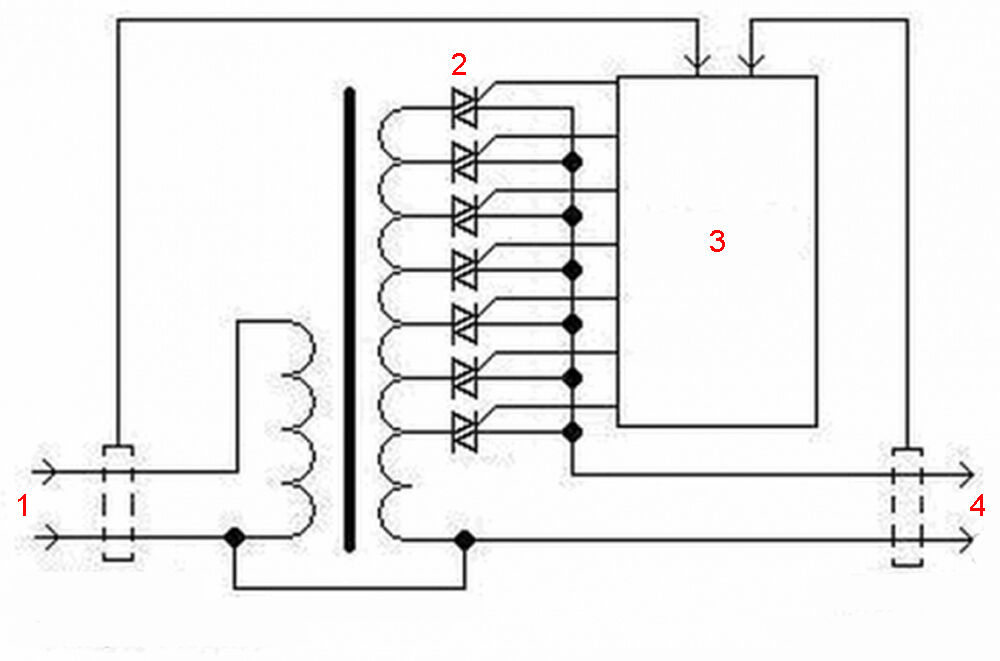
The regulating element of the electronic stabilization circuit is a powerful field-effect transistor of the IRF840 type.The processing voltage (220-250V) passes through the primary winding of the power transformer, is rectified by the diode bridge VD1 and goes to the drain of the IRF840 transistor. The source of the same component is connected to the negative potential of the diode bridge.

The part of the circuit, which includes one of the two secondary windings of the transformer, is formed by a diode rectifier (VD2), a potentiometer (R5) and other elements of the electronic regulator. This part of the circuit generates a control signal that is sent to the gate of the field-effect transistor IRF840.
In the event of an increase in the supply voltage, the control signal lowers the gate voltage of the field-effect transistor, which leads to the closing of the switch. Accordingly, at the load connection contacts (XT3, XT4), a possible increase in voltage is limited. The circuit works in reverse in case of a drop in mains voltage.
Setting up the device is not particularly difficult. Here you will need a regular incandescent lamp (200-250 W), which should be connected to the device output terminals (X3, X4). Next, by rotating the potentiometer (R5), the voltage at the marked terminals is brought to a level of 220-225 volts.
Turn off the stabilizer, turn off the incandescent lamp and turn on the device with a full load (not higher than 2 kW).
After 15-20 minutes of operation, the device is turned off again and the temperature of the radiator of the key transistor (IRF840) is monitored. If the heating of the radiator is significant (more than 75º), you should choose a more powerful heat sink.
If the process of manufacturing a stabilizer seems too complicated and irrational from a practical point of view, you can find and purchase a factory-made device without any problems. Rules and criteria choosing a stabilizer for 220 V are given in our recommended article.
Conclusions and useful video on the topic
The video below examines one of the possible designs for a homemade stabilizer.
In principle, you can take note of this version of a homemade stabilization device:
It is possible to assemble a block that stabilizes the mains voltage with your own hands. This is confirmed by numerous examples where radio amateurs with little experience quite successfully develop (or use an existing one), prepare and assemble an electronics circuit.
There are usually no difficulties in purchasing parts for making a homemade stabilizer. Production costs are low and naturally pay for themselves when the stabilizer is put into operation.
Please leave comments, ask questions, post photos related to the topic of the article in the block below. Tell us how you assembled a voltage stabilizer with your own hands. Share useful information that may be useful to novice electrical engineers visiting the site.


Regarding the transformer used in the stabilizer. Finding a TS-320 is not so easy; less powerful specimens are more often found. But for this purpose it is possible to combine several less powerful transformers, for example, TS-180, TS-200 or others. It is important that the transformers must be of the same type, with very similar parameters. Yes, the device will gain a little in size, but there will be a power reserve.
Good afternoon, Gleb.
If you look specifically for the TS-320, which was used in old TVs, then there will be difficulties. True, the range of dry single-phase circuits is not limited to these models. For example, Promelectrica produces analogues of OSM-1 - power range - 0.063~4 kW. By the way, an analogue of the TS-320 is sold by Elementavia, promising to deliver anywhere in the world.
Regarding the combination of less powerful ones - this is called “parallel operation of transformers” - here, of course, it is easier to buy, but more difficult to select. The “store” does not deal with such things. Let me remind you that among the matching technical characteristics, PUE 2.1.19 regulates:
— coincidence of groups of winding connections;
— power ratio ≤ 1:3;
— transformation ratio scissors ≤ “+/- 0.5%”;
— short-circuit voltage run-up ≤ “+/- 10%”;
— phasing.
For our option, it is essential to comply with the conditions on points 2, 3, 4. This is enough to “bury” your idea. The power reserve, I note, will be limited by the “throughput” of the least powerful transformer.
Where are the winding data of the transformer? Wire diameter?
The scheme does not WORK! A field worker flies out - 5 pieces burned out. It seems to me that the scheme is a scam! The primary winding of the transformer is an INDUCTIVE load. The field switch in this circuit cannot operate in any way on an inductive load. Once again, this is a scam! Prove that this is not so.
Hello. It cannot, so it is separated by capacitor C1 in the circuit. So call him first of all on your invention.
If it is separated by capacitor C1 then there is an error in the circuit diagram.
This point shouldn't exist.
Scam fielder of any power flies out. verified.
It seems to me that it is better to use solid-state relays on simstors as the power element. They've been working for me for several years without any problems. I make the circuits on Arduino plus 155 ID3 for control. Price is a penny.
I wrote the program myself. I ordered an autotransformer for 10 kW, 14 steps. The wiring is standard, an industrial machine type B for 45A, two voltmeters from China for the input and output, and an ammeter for the panel with short-circuit and overload protection functions + a powerful bypass switch. Solid state relays are installed on the heatsink. Only 14 pieces.
There is an error in the circuit - in the switching of the diode bridge vd2, the negative terminal is not connected anywhere, but should be connected to the negative terminal vd1. The capacitor has nothing to do with it.
A ferroresonant circuit with two chokes and a capacitor does not work!
It’s easier to buy a used, dead stabilizer for the price of scrap, and put a powerful transformer there. Well, maybe you'll need a new housing if the transformer is large. Well, replace the penny LMku if it’s dead. I have already made several of these, both for the garage and for the dacha and for my mother-in-law.
Well, it’s more powerful to install relbshki, or solid-state ones.
And if only with a capacitor ¿?
Hello. Please tell me about the transformer part.
As I understand it, winding 1 (1-6) is the primary. The 2nd winding (9-10) is a secondary with a voltage of 6.4-7V with a maximum current of 4.7A or more (if you mean TS-180-320). And winding 3... what is U... judging by C3 x 25V, about 20V... or am I wrong? In a word, I have a TS 180... it has the smallest U 43.5V (7-8)...
I would be grateful for your explanations on how to use the 180th in this scheme.
Hello. Managed to figure out a question about TS 180
Greetings to those who know. I ask for the help of your witchcraft so that I can build a simple stabilizer but not less than 400 watts with rectified current. I already checked the trans. I’ll straighten it with a bridge, but I haven’t thought through the stabilization. I want to charge the lithium block on the 48S
Question for Yuri. Can you go into more detail? This is a painfully practical idea. I do any trances myself, but I haven’t mastered the stabilization on radio elements yet. I recently bought a kilowatt Resanta and then it turned out that it’s not enough - I need 2. Well, I don’t want to strengthen it...
Hello! Can you please tell me what voltages are on the windings of transformer T1?