Connecting a bathroom hood to a light switch: analysis of popular diagrams and detailed instructions
Ventilation in the bathroom is not just desirable, but also a necessary condition for comfortable living.It ensures dryness, prevents the growth of mold, and eliminates unpleasant odors when it comes to a shared bathroom.
Indoor ventilation shafts do not always cope with metabolic processes, so air circulation becomes difficult. Forced exhaust can be achieved by installing a fan in the room.
It is often practiced to connect the hood in the bathroom to the light switch - this way you can combine the use of lighting and a fan. Let's look at the best schemes suitable for self-installation, and dwell in more detail on the process of selecting and installing electrical equipment.
The content of the article:
Connection diagrams for the hood to the switch
After the purchase exhaust fan in the bathroom The question arises about its installation and connection to the home electrical network. Thus, there are many ways to turn on the fan, but two schemes are considered appropriate: connecting the exhaust fan through a single-key switch and pairing it with a two-key device. Each of the schemes can be implemented in two versions, which depend on the type of exhaust device - with or without a timer.
As an alternative method, we present autonomous regulation, carried out using a separate switch.It is used less frequently, since a 2-key regulator is much more convenient to use than two 1-key regulators, and installation is easier and faster.
Option #1 - via a single-key switch
First, let's talk about how you can connect the hood in the bathroom at the same time as the switch. We offer two simple solutions suitable for forced ventilation in the bathroom - both in a separate and in a combined bathroom.
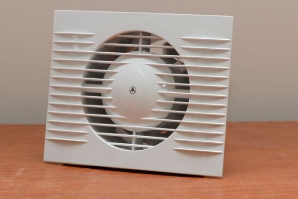
In the first case, we will use an ordinary fan built into the wall hole of the ventilation shaft, in the second - a more advanced model with a timer.
We connect the fan and light to a common switch
The advantage of this method is that it saves space, simpler and faster installation, and just as easy to use. Before entering the bathroom, one switch is installed, to which the wires coming from the lamps and the fan are connected. When you press the key, all devices turn on simultaneously and turn off, respectively, at the same time.

If required, a step-down transformer and power supply are additionally connected to the lamps. Protective grounding is necessary if the luminaire housings are made of metal or have metal elements - this is especially important in a humid environment.
The disadvantage of the circuit is obvious - the fan will rotate only when the lights are on. If ventilation needs to be extended, you will have to leave the lighting on, which means extra costs for electricity bills.

But for some, this method will be the most convenient. For example, for summer residents who live in the house only during the warm season and rarely visit the bathroom. If the family is large, the humidity level in the bathroom is always high, so it is better to use a two-button switch.
Fan with timer and light are connected to the switch
The difference between this option is that we do not use a simple model, but with a timer that regulates the time the hood is turned on/off. We have provided more information about the types of fans in this article.

The advantage of this solution is that you don’t have to leave the lights on to properly ventilate the room. Pressing the key activates both the lighting and the fan, but pressing it again turns off only the lights.
The fan will run for as long as you program it, and then it will automatically turn off.

The circuit works almost flawlessly, but it also has a small drawback - the fan starts rotating even when it is not necessary.For example, if you looked into the bathroom for a minute to turn on the washing machine or use some cosmetics.
For particularly demanding users, the market offers models with two modes, which can be switched by selecting the installation of a jumper - a small jumper, an element of an electronic board.

Thanks to a small but important detail, the hood operates in two modes, which can roughly be called “Toilet” and “Bathroom”.

Let's look at the difference between the two modes:
- "Toilet" – after leaving the bathroom and pressing the switch button, the device will operate for a programmed period, for example, 3 or 5 minutes.
- "Bathroom" – the fan turns on only 90 seconds after the first press of the button. If you are indoors for less than one and a half minutes, it will not turn on. The operating time of the device is programmed in the same way as in the “Toilet” mode.
The second option is convenient if the humidity in the bathroom is low. When you go in just to rinse your hands and quickly leave, the fan does not react at all.
As you can see, even when using a 1-key switch, there are several connection options. Using a hood with a timer significantly increases its capabilities.
Option #2 - via a two-key switch
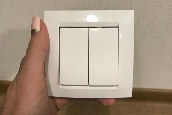
Now let’s consider an option that is a little more difficult to connect, but much easier to use - with a 2-key switch. On sale you can find electrical installation products that are made specifically for this purpose - combining ventilation and lighting circuits.
Connecting the fan and lighting
The main difference between the circuit is the use of a two-key switch. It is mounted in a “phase” break so that one circuit goes to lighting, the second to exhaust.

The advantage of the scheme is the autonomous inclusion of two systems with different functions - ventilation and lighting.
If you do not need to ventilate the room, press one key. If you wish, you can use both keys, and then the fan will work while you are in the bathroom.

The disadvantages depend only on the forgetfulness of the residents. Some users have the habit of pressing all the keys at once - just to be sure to turn on the one they need. In this case, you can get by with a single-key model.
If the fan is quiet, you can simply forget to turn it off - and it will work all night unnecessarily. In such a situation, we can recommend a hood with a timer, which will limit the operation within reasonable limits.
Connect a fan with a timer and light
This scheme should be considered separately, since it differs from the previous one in one important nuance.If everything in the lighting circuit remains the same - a phase wire goes to the lamps from one of the switch keys, then the fan is connected differently.

When connecting a fan, both “zero” and “phase” from the distribution box follow to the fan terminals without a break. And the device is connected to the switch by another “phase”. It is this phase that needs to be connected to the LT terminal - the “phase” contact of the timer.
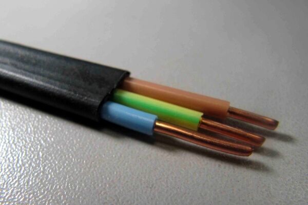
If you take a three-wire wire (which is recommended), then you can use the yellow-green “ground” as the control “phase”. If it is used in a lighting circuit for its intended purpose, then it is absolutely free and can be connected to a timer.
The advantages of the scheme are independent operation of the devices, and the fan will rotate in a clearly defined time period.
Option #3 - installing an additional switch
What to do if the wires are laid deep in the grooves and a beautiful expensive switch has already been installed on the lighting circuit, and suddenly forced ventilation is required?
Near an already installed switch or in another place you can put another one, designed specifically for the fan.

If in other circuits exclusively 3-core wires are used, then “ground” is not required here, since household overhead axial fans are made of plastic. All connections are made with “phase” and “neutral” wires.
Instead of a distribution box, a recessed socket box is often used. The depth is necessary to freely place the connecting terminal blocks and the working part of the switch.
General installation instructions
Whatever scheme you prefer, installing devices and connecting wires is the same. For work, you need to select suitable devices in advance, prepare tools, and if necessary, then drill the walls. We offer step-by-step installation instructions.
Stage 1 - performing “rough” work
The question of forced ventilation arises when residents notice that it is not coping with its tasks. This can be checked in a simple way: if the flame of a match tilts towards the shaft, the hood works; if it is directed vertically upward and does not fluctuate, then the mine needs cleaning.
Before installing the fan, the ventilation duct must be cleaned. We do not recommend doing this on your own, especially if the management company or service organization is responsible for the maintenance of the house. It is necessary to call specialists who will carry out the necessary measures.
Bathroom, according to PUE (clause 1.1.13) are classified as high-risk premises, since the humidity level reaches 60% or more. This means that all electrical appliances must have special protection, and wires and contacts must be hidden from direct splashes of water.

To disguise wires in the walls, even before finishing, grooves are laid - channels for electrical wiring. If you are planning to do repairs, then it is better to install the fan simultaneously with the installation of other electrical appliances.
So, the “rough” work consists of cleaning the shaft and gating the walls for wiring. Additionally, you need to prepare a hole in the wall for installing the fan and make recesses for electrical outlets and distribution boxes (if necessary).
Stage 2 - preparation of tools and materials
Electrical installation work usually does not require the use of any special tools - usually even amateurs have everything they need.
The selection of materials should be taken very seriously - after electrical installation work, the bathroom is finished, most often expensive, which you will not want to disturb for the next 10-15 years. All wires, electrical installation products, devices and consumables must be of high quality, factory-made, with a guarantee.
The minimum required for the hood device:
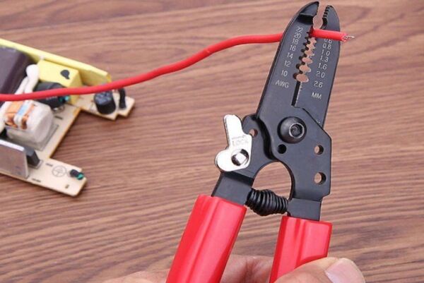
If you decide to crimp the wires with sleeves, then prepare both pliers and sleeves in advance. But soldering wires is used less and less due to the complexity and duration of the process itself.
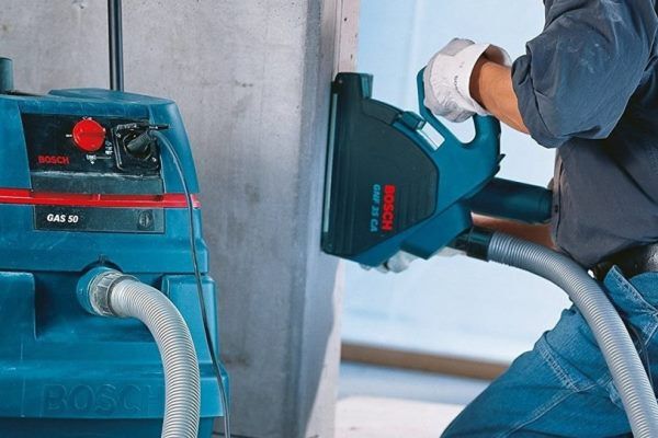
You may also need a construction vacuum cleaner from equipment, and sealant from materials.
Stage 3 - completing the connection process
You should start by installing the fan. We stretch the wires through the channels in advance - from the switch to the hood and the installation locations of the lamps. For protection, all cables located in the bathroom space can be enclosed in corrugated insulating pipes.

The fan is either “mounted” on self-tapping screws (dowels) or fixed with sealant. In the first case, it is easier to dismantle it, but during installation you can damage the cladding if it is already done.
Work order:
- We unscrew the decorative panel of the device and remove it along with the mosquito net.
- We position the cable in the shaft so that it does not interfere with air circulation, and remove the corrugation from the ends of the wires.
- We lead the power cable into a specially designed hole.
- We install the fan in place, tighten the screws.
Before attaching the decorative panel, we make the connection.

The final step is to install the decorative cover by tightening the fastening screw. As a result, all wires must be hidden in the device or in the wall.
We connect the switch cores according to the selected diagram; the designations on the diagrams are traditional.
The situation in the fan was as follows:
- red — terminal L;
- blue — terminal N;
- yellow-green - T or LT.
We recommend that you read in more detail color coding of wires in electrics.
What do experienced electricians advise you not to do?
First, don't connect your bathroom fan directly to a light bulb. Then you will deprive yourself of comfort - the fan will always work only when the light is on, including when you take a bath.
Secondly, it is still not recommended to install the switch indoors. If the project requires confirmation from the appropriate authority, you simply will not receive it.
Thirdly, it is not recommended to use complex electrical devices and all kinds of sensors. They often break due to high humidity, take up space on the walls and do not look very aesthetically pleasing. The simpler the devices and connections, the fewer problems there are with them.
Conclusions and useful video on the topic
Details about installing a hood in simple language:
Nuances of installation on tiles:
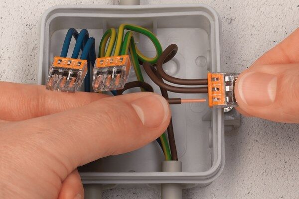
Instructions for using Vago terminals:
Recommendations for choosing a fan, testing:
If you are planning to renovate your bathroom yourself, including upgrading the lighting system, then installing a fan will seem like a quick and easy task. The main thing is to decide at the start about the operating mode of the hood, choose a reliable model and correctly connect it to a one- or two-button switch.
Remember: whatever scheme you prefer, installation should be carried out in accordance with generally accepted requirements and safety rules.


