About methods of control by gauges of cylindrical pipe threads
In recent years, bimetallic radiators with steel collectors and an external aluminum casing have rightfully become increasingly popular among sectional heating devices.In accordance with European technologies, the internal threads of heating devices from most manufacturers are made using the rolling method. Rolled threads provide a durable and safe threaded connection, as evidenced by many years of successful use of bimetallic radiators.
In accordance with GOST 31311-2005 “Heating devices. General technical conditions" (clause 8.2.) threaded connections of heating devices are tested with thread gauges. At the same time, individual radiator manufacturers using threaded technology, as well as non-profit industry associations, have repeatedly proposed/appealed to various government bodies, departments, and services with a requirement to additionally check the internal threads with smooth gauges.
This paper examines the validity of these proposals and the advisability of introducing such an additional requirement using the example of the G1 thread, which is used on most heating devices.
First, let's look at the basic requirements for making pipe threads.
- The parameters of cylindrical pipe threads are determined by GOST 6357-81 “Basic standards of interchangeability. Cylindrical pipe thread”, according to which:
The nominal thread profile and the dimensions of its elements must correspond to those indicated in Drawing 1:
Drawing 1
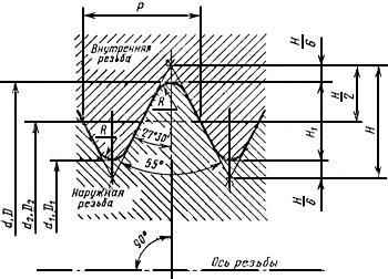
The dimensions of the above indicators in millimeters for the G1 thread are shown in Table 1:
Table 1
| Step P | N | H1 | R | |||
| 2,309 | 33,249 | 31,770 | 30,291 | 2,217774 | 1,478515 | 0,317093 |
At the same time, according to the same GOST 6357-81, it is allowed to make threads with deviations from the specified values (tolerances), subject to which the thread will also comply with GOST 6357-81.
Schemes of tolerance fields for external and internal threads are shown in Drawing 2.
Deviations are counted from the nominal (ideal) thread profile in the direction perpendicular to the thread axis.
Drawing 2
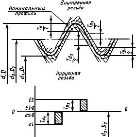

— diameter tolerances d, d2, D1, D2
The numerical values of the tolerances for the diameters of external and internal threads must correspond to those given in Table 3:
Table 3
| Thread size designation | Pitch P, mm | External thread | Internal thread | ||||
| Thread diameters | |||||||
| outer diameter of male thread | average diameter of external thread | average internal thread diameter | internal diameter of female thread | ||||
| Tolerances, microns | |||||||
| Td | Td2 | TD2 | TD1 | ||||
| Class A | Class B | Class A | Class B | ||||
| G1 | 2,309 | 360 | 180 | 360 | 180 | 360 | 640 |
Note that, according to Table 1, the value of H1 (working height of the thread profile) is equal to 1.478515 mm, and, in accordance with Table 3, the tolerances on the internal diameter of the internal thread D1 and the external diameter of the external thread d are 640 μm and 360 μm, respectively . Drawing 3 shows internal and external thread profiles G1, made with the maximum permissible deviation from the nominal profile in accordance with Table 3. Moreover, these thread profiles fully comply with the requirements of GOST 6357-81.
Drawing 3
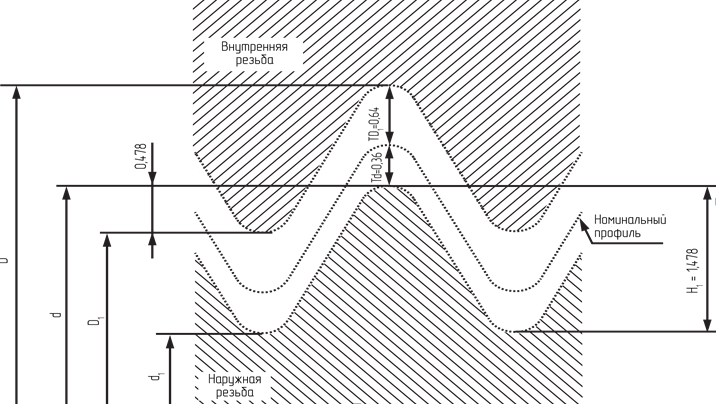
The drawing clearly shows that in this case only 32.4% of the thread profile height is involved in the threaded connection.
In this regard, the position of some manufacturers of heating devices, as well as specialized industry associations, which consider it unacceptable to recognize a thread as acceptable if the thread profile is only 38% of the nominal value, is especially surprising. Apparently, these manufacturers and associations simply do not understand the elementary fundamentals of GOST 6357-81 in terms of which thread (with what dimensions) is considered made in accordance with this GOST.
In our opinion, the need for such significant tolerances is associated with the requirement of paragraph 5.1.6 “SP 73.13330.2016 Internal sanitary systems of buildings”, according to which “When assembling units, threaded connections must be sealed.
As a sealant for threaded connections at temperatures of the transported medium up to 378 K (105°C), it is recommended to use FUM tape or flax strands in accordance with GOST R 53484, impregnated with red lead or white lead., mixed with natural drying oil, or special sealing pastes-sealants.”
Now let’s move on to consider the main issue of this article: how advisable is it to include in the regulatory documentation regarding control of threads of heating devices a requirement for mandatory inspection of internal threads with smooth gauges.
Let's analyze the proposal for monitoring the internal threads of heating devices using a smooth pass-through gauge:
Let's consider the ideal option when the internal thread is made in strict accordance with GOST 6357-81, i.e. ideally according to the nominal profile without any tolerances. In this case, according to Table 2, the internal thread diameter will be 30.291 mm.
Let's try to check this thread with a smooth pass gauge.
In accordance with clause 6.2. GOST 2533-88 “Gauges for pipe threads. Tolerances" diameter sizes of smooth gauges for testing external and internal threads should be determined according to the formulas given in Table 4.
Table 4
| Designation (type number) caliber | Name and purpose of the caliber type | Caliber diameter | |
| Denomination | Maximum deviation | ||
| Internal thread gauges | |||
| PR (23) | Smooth pass-through plug gauge |  |  |
| NOT (24) | Smooth no-go plug gauge |  |  |
The values of indicators H1 and Z1 are given in Table 5.
Table 5
| TD1 value according to GOST 6357 | H1, µm | Z1 |
| from 375 µm to 710 µm | 26 | 52 |
From the analysis of the data in the tables above, it follows that the diameter of the smooth passage gauge will be equal to:
- nominal value: D1+ 52 µm = 30.343 mm
- value with maximum upper deviation: D1+ 52 µm + 13 µm = 30.356 mm
- value with maximum lower deviation: D1+ 52 µm - 13 µm = 30.330 mm
Note that, according to clause 2.3. Appendix 2 “Rules for the use of gauges” to GOST 24939-81 “Gauges for cylindrical threads”, “a smooth pass gauge must freely enter the controlled thread under the influence of its own weight or a certain force.”
In this regard, we get a paradoxical picture in which a smooth, wear-free pass-through gauge, the minimum possible diameter of which is 30.330 mm, should freely fit into a thread ideally made according to GOST 6357-81, the diameter of which is 30.291 mm (nominal), which basically impossible.
Thus, when checking a thread perfectly made in accordance with GOST 6357-81 with a smooth go-through gauge, this thread will be recognized as not complying with GOST 6357-81, which in itself is absurd.
This partly explains the cases when threaded connections made in accordance with GOST 6357-81 class A, which require more precise threading in terms of permissible deviations (tolerances), are rejected when tested with a smooth pass gauge.
Taking into account the above, we can conclude that the introduction of an additional requirement for checking the internal threads of heating devices with smooth go-through gauges will not only not ensure control over the execution of threads in compliance with GOST 6357-81, but, on the contrary, will lead to an absurd situation when those made in full accordance with the requirements GOST heating devices will be considered defective.
Next, let us analyze the proposal for monitoring the internal threads of heating devices using a smooth non-go through gauge:
Let's consider the option when the internal thread is made in full compliance with GOST 6357-81, but with the maximum tolerance provided by GOST - 640 microns (see indicator TD1 Table 3). In this case, the internal thread diameter will be 30.931 mm.
Let's try to check this thread with a smooth no-go gauge.
From the analysis of the data given in Table 4 and Table 5, it follows that the diameter of a smooth no-go gauge will be equal to:
- nominal value: D1+ 640 µm = 30.931 mm
- value in the maximum upper deviation: D1+ 640 µm + 13 µm = 30.944 mm
- value in the maximum lower deviation: D1+ 640 µm - 13 µm = 30.918 mm
Note that, according to clause 2.4. Appendix 2 “Rules for the use of gauges” to GOST 24939-81 “Gauges for cylindrical threads”, “a smooth no-go gauge should not enter a controlled thread under the influence of its own weight or a certain force.”
In this regard, we again get a paradoxical picture in which a smooth, wear-free NON-pass gauge, the minimum possible diameter of which is 30.918 mm, should NOT freely fit into a thread made according to GOST 6357-81 with maximum tolerances, the diameter of which is 30.931 mm , which is basically impossible.
Thus, when checking a thread made in accordance with GOST 6357-81 with a smooth NON-GOING gauge, this thread will be recognized as not complying with GOST 6357-81, which in itself is absurd.
Taking into account the above, we can conclude that the introduction of an additional requirement to check the internal threads of heating devices with smooth non-go-through gauges will not ensure control over the execution of the threads for compliance with GOST 6357-81.
Thus, the above analysis clearly indicates that the use of smooth gauges is not only not capable of unambiguously establishing the compliance or non-compliance of a thread with the requirements of GOST 6357-81, but may also lead to the recognition of a thread that fully complies with this GOST as defective.
The rules for using smooth gauges themselves are of particular interest. They are set out in GOST 24939-81 “Gauges for cylindrical threads” (Appendix 2 “Rules for the use of gauges”).
Thus, for a smooth go-through plug gauge there is a requirement that the gauge must freely enter the controlled thread under the influence of its own weight or a certain force, and for a smooth non-go through plug gauge there is a requirement that this gauge must not enter the controlled thread under the influence of its own weight or a certain strength.
At the same time, neither the Rules for the Use of Calibers, nor GOST 24939-81, nor any other regulatory documents establish who and how should determine the magnitude of this force, and in what direction it should act on the caliber.
From this we can draw an unambiguous conclusion, according to which there is no single methodology for using calibers established by the relevant regulations.
In addition, in our opinion, when discussing the requirements for testing the threads of heating devices, it is advisable to consider similar conditions of the standards for heating system elements directly connected to heating devices.
So, in section “2. Regulatory references" GOST 30815-2002 "Automatic thermostats for heating devices of water heating systems in buildings" GOST 6357-81 is mentioned, however, it is not used further in the text. Perhaps for this reason, in the new edition of GOST 30815-2019, GOST 6357-81 is completely absent from the list of regulatory references.
In addition, in GOST 21345-2005 “Conical and cylindrical ball valves” GOST 6357 is also not mentioned.
Thus, in the standards GOST 30815-2019 and GOST 21345-2005 for elements of heating systems directly connected to heating devices, there are no requirements for testing threads for compliance with GOST 6357-81.
In this connection, it is not clear what exact goal is pursued by the authors of proposals to control the threads of heating devices using additional smooth gauges without establishing any control at all on the threads of elements of heating systems directly connected to heating devices.
In our opinion, it is absolutely pointless to conduct any discussion of the use of smooth gauges for monitoring the internal threads of heating devices in the presence of:
- the discrepancies between the nominal diameter of the internal thread and the nominal diameter of the smooth bore specified in this article,
- lack of a unified approved methodology for using calibers,
- the absence of any requirements for threads and methods of its control in relation to elements of heating systems directly connected to heating devices.
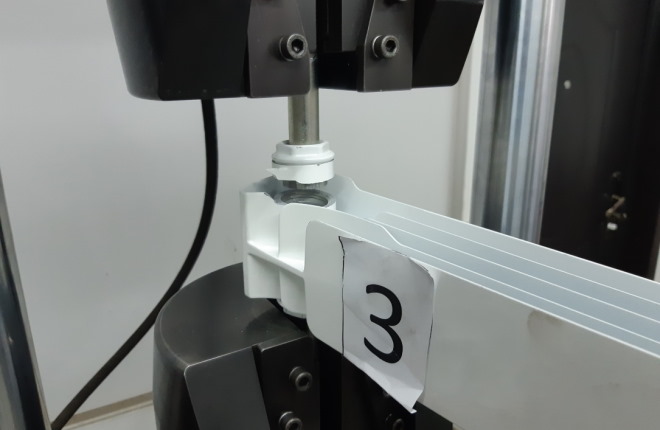
Additionally, in order to establish the dependence of how the results of testing with smooth gauges affect the strength of threaded connections of heating devices, we conducted a series of tests. Eight samples of three types of radiator sections were selected for testing:
- aluminum (AL),
- bimetallic with steel vertical and horizontal heat-conducting channels (BM),
- aluminum radiators with steel vertical heat-conducting channels (ASVK).
All samples were tested with threaded (go and no-go) gauges, and were additionally tested with smooth gauges. The results of testing with smooth gauges are shown in Table 6.
Samples 7 and 8 were selected so that the non-passing smooth gauge fit freely without effort with a slight backlash into the threaded hole of the radiator sections. The samples were screwed with screw plugs recommended by the radiator manufacturer. Static tensile tests were carried out until samples failed in a certified laboratory.
Table 6
Static tensile test results
| Sample number | Radiator type | Checking with a smooth pass gauge | Checking with a smooth no-go gauge | Breaking load, N | Limit of proportionality. Bar |
| 1 | BM | negative | positively | 48 791 | 604,10 |
| 2 | ASVK | positively | positively | 41 884 | 525,71 |
| 3 | ASVK | positively | positively | 35 309 | 444,65 |
| 4 | BM | positively | positively | 108 272 | 1249,13 |
| 5 | AL | positively | positively | 39 924 | 502,09 |
| 6 | BM | negative | positively | 102 473 | 1061,17 |
| 7 | BM | positively | negative | 46 272 | 563,17 |
| 8 | BM | positively | negative | 52 987 | 619,63 |
The test results are confirmed by official protocols of the testing laboratory, video and photo shooting.
Using the example of sample No. 4, it is clearly visible that when testing a bimetallic radiator, deformation occurs in the threaded connection.
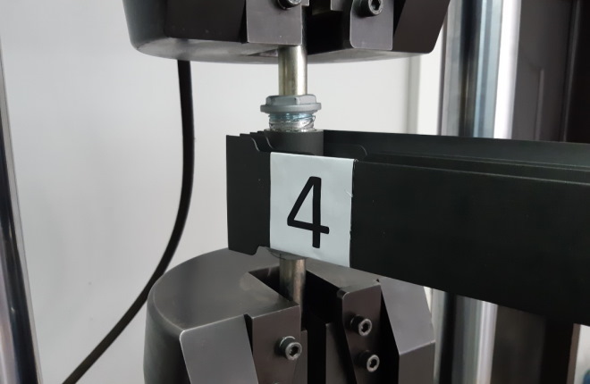
When testing an aluminum radiator and a radiator with a steel heat-conducting channel, destruction occurred in the body of the radiator section.
From the given data it follows that the thread of a heating radiator that has not been tested with a smooth go-through (sample 1, 6) or non-go through (sample 7, 8) gauge, but fully complies with the requirements of GOST - 6357, when tested with thread gauges, forms such a threaded connection, the limit the proportional deformation of which many times exceeds the pressure values that other elements of heating systems can withstand.
It is also indicative that radiators whose threads were not tested with any smooth gauge, in terms of reliability and safety in terms of destruction of the threaded connection, showed similar, and in some cases, better results compared to those radiators whose threads were tested both smooth calibers.
This once again proves that checking the threads with smooth gauges in no way affects the strength of the threaded connection of the heating radiator and, as a consequence, the safety and reliability of this device.
Moreover, for samples No. 7 and No. 8, the failure load of the threaded connection turned out to be higher than the failure load of the body of the aluminum radiator section and the radiator with a vertical steel channel. It is especially significant that aluminum radiators with a steel vertical channel showed worse results than a conventional aluminum radiator.
Based on all of the above in this article, we can make an unambiguous conclusion that the currently provided methods for monitoring the internal threads of heating devices using only thread gauges (clause 8.2. GOST 31311-2005) are more than sufficient for the production of heating devices that are reliable and safe for consumers. devices.