Do-it-yourself pyrolysis boiler: device, diagrams, principle of operation
The term “pyrolysis” refers to a process in which the slow combustion of solid fuel takes place to produce a gaseous medium.Despite the “professorial” name of the structure, making a pyrolysis boiler with your own hands is relatively easy, and homemade products are quite common in practice.
The explanation for this is simple - a wood-burning gas generator boiler is easier to maintain, often more efficient and economical than other similar equipment. Let's figure out together how such equipment works and what is needed to make it.
The content of the article:
Operating principle of pyrolysis boilers
Boilers for heating systems, where solid combustible materials are used as fuel, in addition to the classics, also belong to pyrolysis structures. They are usually called gas generator boilers.
To better understand the operating principle of a home pyrolysis boiler, it is logical to carefully consider the design of such equipment. Let's start with the features of the firebox as the main part of the heating structure. Essentially, the working area of the fuel chamber of pyrolysis boilers is divided into two separate chambers.

One of these chambers is loaded with solid fuel - firewood, pellets, briquettes, etc. There the primary process of solid fuel combustion begins with a limited air supply. In this state, the fuel does not burn, but smolders.The gases released during slow combustion enter another area of the chamber - the active one, where, with an increased air supply, they burn out intensively.
Technically, such a combustion process is implemented in a simple way. The subregions of the common chamber are simply separated by a grate and a nozzle. The upper part of the chamber is a passive firebox, the lower part of the chamber is an active firebox. In this case, one should take into account the design feature - the upper air supply to the fuel chamber (top blast).
Actually, this is what distinguishes the design of a gas generator boiler from the classic single-chamber design, where bottom feed is used.

Technologically, the organization of forced draft is also a characteristic feature of the design of pyrolysis boilers. The design of the two-stage firebox has increased aerodynamic resistance. Therefore, there is no way to do without installing an air pump.
How does a boiler function in practice?
It is convenient to consider the practical application of the equipment in a step-by-step process:
- Loading firewood - placing the upper area of the chamber on the grate.
- Ignition the fuel and start the smoke pump.
- Formation of wood gas at a temperature of 250-850 °C.
- Transition of wood gas to the lower area of the firebox.
- Combustion of wood gas with additional air supply.
Next, the heat obtained in the lower region of the fuel chamber is used to heat the coolant. The coolant can be either water or air.

If you pay attention to all the existing designs of domestic boilers operating on solid fuel, the main alternative to a pyrolysis boiler is the design of a traditional design.
This is a similar version of a wood-burning boiler, where there is one undivided firebox and the principle of lower air supply into the combustion chamber operates. But such a system is considered less efficient and uneconomical due to the rapid combustion of fuel.
A pyrolysis boiler is capable of delivering an efficiency of 85-95% at 100% load. However, efficiency drops sharply if the load is less than 50%. That is why manufacturers of pyrolysis equipment recommend that users operate the equipment at maximum load.
A similar approach is also valid for home-made structures, provided they fully comply with the classical pyrolysis scheme and operating requirements.
For “pyrolysis”, the operating requirements, it should be noted, are quite stringent:
- mandatory equipment with an air pump;
- permissible fuel moisture content is not higher than 25-35%;
- the load on the equipment is not lower than 50%;
- return coolant temperature is not lower than 60 °C;
- loading only with large fuel arrays.
It should also be noted that it is expensive pyrolysis systems industrial production. This is probably why the do-it-yourself option is so popular.
Homemade pyrolysis boiler
As a rule, when making such heating equipment with your own hands, the popular Belyaev scheme is taken as a basis. This is not to say that this is a simple solution that allows you to make a heater without problems. But, perhaps, one of those solutions that can really be implemented.

To produce equipment according to this scheme, the master will need:
- metal pipe (d = 32; 57; 159 mm);
- profile pipe (s = 60x30; 80x40; 20x20 mm);
- steel strip (20x4; 30x4; 80x5 mm);
- fireclay brick;
- a metal sheet;
- air pump;
- temperature sensor.
You also need to have a full set of plumbing tools, plus a welding machine (and welding skills, respectively). The work of making a pyrolysis boiler with your own hands is clearly not something you can do alone. At least one assistant is needed.
First of all, in accordance with the chosen scheme, it is necessary to prepare the sheet parts of the structure. It is recommended to prepare sheet panels by cutting them to size using professional precision equipment.
The use of hand tools such as “grinders” for cutting also requires some work skills and compliance with safety regulations during operation, but does not ensure cutting accuracy, which subsequently affects the quality of welding. This point should be taken into account. A reasonable solution for cutting metal sheets is to order it from a mechanical workshop.
Assembly of internal parts of equipment
It is necessary to make a fuel chamber from one part of metal sheets.To do this, a material commensurate with the circuit parameters is connected and welded. The result should be a two-chamber structure, which should be supplemented with air ducts.
These elements of the fuel chamber are made from a metal channel or a profile pipe is used for manufacturing. Holes are drilled across the entire area of the front side of the air duct.

Below the level, in the area of the active combustion chamber, on the wall located across the air ducts, a metal pipe (secondary air supply) is embedded. Next, work begins with the pipes, since the turn of assembling the tubular heat exchanger has come.
This part of the pyrolysis system is made from metal pipes d=57 mm:
- Take two metal sheets according to the size of the drawing and make markings.
- Based on the markings for the location of the pipes, holes d = 60 mm are cut out on the sheet.
- Pipes d=57 mm are cut to length.
- The ends of the pipes are inserted into the holes of one sheet and scalded.
- Repeat the operation with another sheet.
The output should be a finished heat exchanger, which is attached to the boiler body where the diagram indicates.

A throttle valve is installed next to the heat exchanger (at the upper level). This part is equipped with a handle and is also welded to the structure.The end part of the throttle body is covered with a piece of sheet with a pipe for the chimney.
Next, all that remains is to weld the front panel of the fuel chamber with windows for the doors under each of the two sections and a module for the air pump.

Before installing the front panel, the inside of the combustion chambers must be reinforced with fireclay bricks. This material is cut to size, some of it at an angle. The brick is ground and adjusted to the location where it is laid.
Both working sections of the boiler fuel chamber are treated with fireclay bricks. At the same time, the areas of the dampers of the air outlet (supply) pipes are carefully lined. After laying the brick, the front panel is installed.

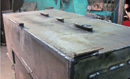
In fact, the main assembly of the pyrolysis boiler at this stage can be considered complete. The assembled structure must be processed - remove scale from welding, clean welds, straighten if there are small irregularities somewhere.
The next stage is enclosing the assembled structure in a sealed housing. This part of the structure is also made of metal sheets. However, crimping is required first.
Testing and final assembly of the structure
The assembled structure must be tested. Mandatory actions - check for tightness of the area of the boiler where the coolant should circulate.To carry out pressure testing of the heat exchanger, plugs are temporarily installed on the coolant supply and return pipes.
Then the heat exchanger is filled with water. It is advisable to use hot water from the heating network or hot water supply in order to be able to check the welds under conditions of thermal expansion of the metal.

Provided there are no leaks at the seams of the heat exchanger, the water is drained and they begin to frame the structure of the pyrolysis boiler with external metal panels. Also at this stage, the doors of the windows of the combustion chamber sections are manufactured and hung.
The doors of a pyrolysis unit require design taking into account high-temperature operating conditions. Therefore, these structural elements are usually made (or used ready-made) from cast iron with additional temperature reinforcement with fireclay bricks.

The final stage is the installation of a pyrolysis boiler at the place of its future operation. The structure is installed on a foundation or on a concrete slab. It is recommended to maintain the height of the foundation (slab) relative to the ground level at a size of no less than 100 mm.
After installation and level balancing, the lower part of the boiler is fixed to the foundation. All that remains is to connect the chimney pipe, install the air pump and connect the coolant supply/outlet lines.
Making a pyrolysis boiler structure yourself is a job that requires a significant investment of effort. Of course, you cannot do without overhead costs in terms of financial resources.
It is possible that the cost of purchasing material and using third-party services will be less than the cost of industrially manufactured equipment. However, the difference most likely will not be so significant. But the main issue is not money.
Conclusions and useful video on the topic
About independent production of a pyrolysis boiler:
Technically, independent production of pyrolysis boilers without the appropriate base is an extremely complex process. Professional skills in working with metal, a clear understanding of engineering schemes and technological subtleties of manufacturing boiler equipment are also required. Without all this, you shouldn't even get to work.
If you have the necessary knowledge and skills, and can give valuable advice on assembling a pyrolysis boiler to other site visitors, please leave your comments, share your secrets of skill, and ask questions in the block below the article.


At the stage of building a house, I decided to buy a pyrolysis boiler, like it can process any type of fuel and has high efficiency. But I went shopping, looked at the prices and changed my mind. The boilers that are cheaper are kind of thin-walled, but I couldn’t afford the expensive imported ones.
I definitely won’t do it myself, you have to be a professional welder, but I weld at the household level.Well, the investment in metal, pipe, and additional tools is also considerable. Although, when you do it yourself, for yourself, you are sure of the quality, that’s for sure.