How to check a three-way valve in a gas boiler: instructions for checking the valve yourself
A three-way valve is a device widely used in a wide variety of designs of household and industrial devices.Accordingly, the same type of device is used as part of household gas equipment. Along with various malfunctions of domestic gas boilers, users often encounter a breakdown of the three-way valve. Agree, it would be nice to find out why this device fails and try to fix it on your own.
Meanwhile, even professional mechanics are not always able to determine the loss of functionality of a device “at first glance.” This requires appropriate verification. Therefore, in our article we will consider how to check a three-way valve in a gas boiler when there is a suspicion of a malfunction of this mechanism. We will also talk about the types of device and its functionality.
The content of the article:
Brief introduction to the three-way valve mechanism
The design of a three-way valve for a domestic gas boiler and other gas equipment is quite simple, despite its complex, at first glance, shape. It should be noted that the design of the valves differs significantly for each manufacturer, but the principle of operation actually remains unchanged.
Traditionally device body made of bronze. Work items, e.g. stock, springs - made of steel. Membrane usually made of rubber Used to seal the rod double ring element. Connecting parts (fittings) can be threaded or soldered, depending on the model of the three-way valve.
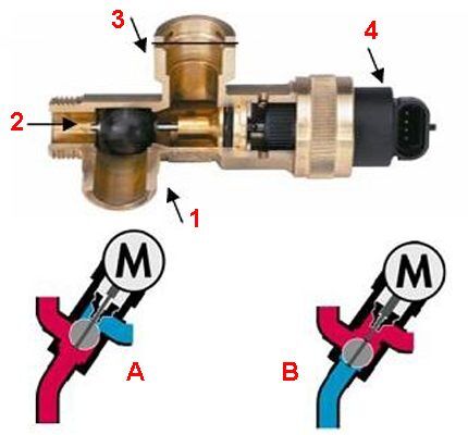
Typically, an electromechanical drive is used in conjunction with the device. Thanks to its operation, two-point regulation is carried out.
Thus, the drive of a three-way valve can be manual, electromechanical (thermostatic, with a thermal head), electric, or hydraulic.
The operating principle of a three-way valve for a gas boiler circuit is approximately the following: when the device is in the normally open transport mode, the direct through transport channel is, accordingly, open. The corner passage channel remains closed.
A different state of the mechanism ensures the opening of the angular transport channel and blocking of the direct transport channel, respectively. Intermediate positions of the three-way valve stem and flap are also possible.
We talked in more detail about the design and operating principle of a three-way valve in next material.
Functional application of the device
If we consider the flow switching mechanism from the point of view of possible functionality, it should be noted that the devices differ in their operating principle:
- Dividing.
- Switching.
- Mixing.
The separation principle of operation involves dividing the flow, directing it into two circuits.
The switching function provides for the organization of switching between devices that consume thermal energy. For example, switching between DHW and heating circuits double-circuit gas boiler.
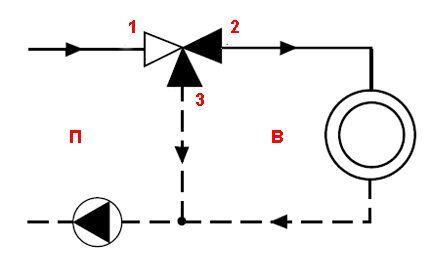
The switching functionality allows you to organize efficient switching between various devices that generate thermal energy:
- water heaters;
- heat pumps;
- solar panels, etc.
Another function of a three-way valve for a domestic gas boiler is mixing. It allows you to organize controlled mixing of working fluid flows (mixing return flow into the heated coolant).
To do this, it is enough to install a three-way valve on the return pipe of the heating system.
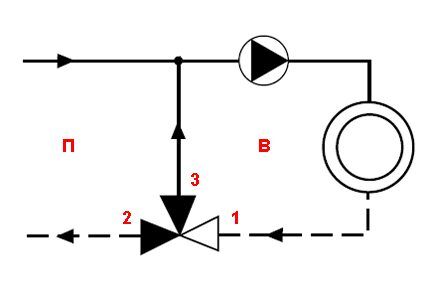
Now, after a brief introduction to the design details of the device, we can consider the features of checking the operation of a three-way valve installed in gas boiler diagram.
How is a three-way valve checked?
Malfunction of the device affects the operation of the gas boiler as a whole. For example, if the coolant supply is insufficient, the gas boiler may simply turn off due to overheating. Or, a malfunction of the three-way valve may be accompanied by a lack of proper heating temperature of the coolant in the heating system.
In any case, the device needs to be checked for functionality. At the same time, to carry out diagnostic measures, the gas boiler control device, as a rule, has to be dismantled. Dismantling is relatively simple, so such work can easily be done on your own.
Step #1 - Valve Actuator Check
Next, we will consider the verification process step by step, starting with checking the drive. Let's consider the features of diagnosing valves with different types of drive.
Diagnostics of the three-way valve electric drive
The valve stem is traditionally controlled by an electric actuator. Therefore, the integrity, availability of power, and operability of the electric drive should be checked first.
The integrity of the external part is checked visually through careful inspection, and the presence of power and the integrity of the internal mechanism are checked with appropriate instruments.
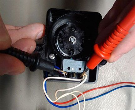
The drive and all elements of this part of the structure are usually diagnosed with an electrical tester. This device can check both the integrity of the circuits and the presence of supply voltage. When the supply voltage is applied/disconnected, a serviceable drive should demonstrate a working process - movement of the valve rod pusher.
It is permissible to check the operation of the electric drive by directly connecting the mechanism to the electric current network, using the connector that comes with the drive. This point is clearly illustrated in the video located at the end of the article.
Checking the thermostatic head
If the design of a three-way valve does not provide for an electric drive, but is controlled thermostatic head, you need to check this part of the system by applying temperature directly to the sensor bottle.
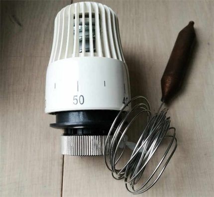
For example, you can heat the thermostatic head bottle using an electric hair dryer.
A working thermal head should respond to temperature changes and push/pull the valve stem in the same way as an electric actuator does this work.
Checking the hydraulic drive device
If the gas boiler system uses a valve that regulates flows and operates on the principle of hydraulic rod control, it is quite difficult to diagnose the performance of such a device directly in the boiler system.
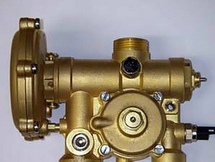
Typically, this type of structure must be dismantled and disassembled, followed by an integrity check:
- springs;
- seals;
- membranes;
- rings
Suspicions about the inoperability of the three-way valve, in this case, can be confirmed by starting the gas boiler in test mode. If at the same time there is a violation of the thermal distribution along the working circuits of the system, 90% of the valve does not work correctly.
Step #2 - checking the thread distribution mechanism
The mechanism of the device can wear out as it is used. In addition, when transporting coolant, it is typical for various debris, deposits, etc. to accumulate in the system.
All this can block the operation of the device. Therefore, first of all, it is necessary to visually checking all available parts.
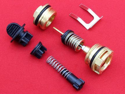
Next is executed checking the normal movement of the diaphragm rod. As a rule, when in working condition, the rod moves smoothly, with some tension.The correctness of the stroke can be checked by exerting a slight force on the end part of the rod (the outlet for the actuator), which exits through the hole in the valve body capsule.
If there are no wedge factors in the stroke of the rod along the entire length and the rod independently returns to its original position from the stop point, then this part of the switchgear is operational.
Finally, seal elements are checked – ball or membrane, depending on the design. While defects on rubber sealing membranes usually appear in the form of tears, ball seals can become deformed over time. The deformation factor leads to the loss of a complete seal, and accordingly, the flow control algorithm of the device is disrupted.
Conclusions and useful video on the topic
Below is a useful video for your reference, which demonstrates the disassembly of a device that regulates heat flows in a gas boiler. Moreover, the practice of disassembling it yourself is given.
The distribution device described in the video is equipped with a hydraulic rod drive. Familiarization with this repair practice will help you understand how to check devices of a similar type and repair if there are defects.
Thus, a three-way valve for a domestic gas boiler can be tested in almost any design, regardless of individual design. The main point is to correctly determine which drive the gas boiler switchgear is used with. Information on this issue can be obtained from the documentation for the equipment or by relying on the drive demonstration examples in this article.
Do you have useful information on the topic discussed above and want to share it with other users? Write your remarks and comments in the block below, add photos, leave your recommendations - the feedback form is located below.


Question: why does the pressure in the water supply system increase when the Viland 282 3-5 boiler is operating in DHW mode. The pressure begins to rise at temperatures above 70 degrees and can reach limit values at T = 85.