Hydraulic calculation of a gas pipeline: methods and methods of calculation + calculation example
For safe and trouble-free operation of the gas supply, it must be designed and calculated.It is important to perfectly select pipes for mains of all types of pressure, ensuring a stable supply of gas to the devices.
To ensure that the selection of pipes, fittings and equipment is as accurate as possible, a hydraulic calculation of the pipeline is performed. How to make it? Admit it, you are not too knowledgeable about this issue, let's figure it out.
We offer you to familiarize yourself with carefully selected and thoroughly processed information about options for producing hydraulic calculations for gas pipeline systems. Using the data we present will ensure that the devices are supplied with blue fuel with the required pressure parameters. Carefully verified data is based on the regulations of regulatory documentation.
The article describes in great detail the principles and schemes for performing calculations. An example of performing calculations is given. Graphic applications and video instructions are used as a useful informative addition.
The content of the article:
Specifics of hydraulic calculation
Any hydraulic calculation performed is a determination of the parameters of the future gas pipeline. This procedure is mandatory, as well as one of the most important stages of preparation for construction. Whether the gas pipeline will function optimally depends on the correctness of the calculation.
When performing each hydraulic calculation, the following is determined:
- necessary pipe diameterthat will ensure efficient and stable transportation of the required amount of gas;
- Will the pressure loss be acceptable when moving the required volume of blue fuel in pipes of a given diameter?
Pressure losses occur due to the fact that there is hydraulic resistance in any gas pipeline. If calculated incorrectly, it can lead to consumers not having enough gas for normal operation in all modes or at times of maximum consumption.
This table is the result of a hydraulic calculation carried out taking into account the given values. To perform calculations, you will need to enter specific indicators in the columns.
| Beginning of the section | End of the section | Estimated flow m³/h | Gas pipeline length | Inner diameter, cm | Initial pressure, Pa | Final pressure, Pa | Pressure drop, Pa |
| 1 | 2 | 31,34 | 120 | 9,74 | 2000,00 | 1979,33 | 20,67 |
| 2 | 3 | 31,34 | 150 | 9,74 | 1979,33 | 1953,48 | 25,84 |
| 3 | 4 | 31,34 | 180 | 7,96 | 1953,48 | 1872,52 | 80,96 |
| 4 | 5 | 29,46 | 90 | 7,96 | 1872,52 | 1836,2 | 36,32 |
| 5 | 6 | 19,68 | 120 | 8,2 | 1836,2 | 1815,45 | 20,75 |
| 6 | 7 | 5,8 | 100 | 8,2 | 1815,45 | 1813,95 | 1,5 |
| 4 | 8 | 9,14 | 140 | 5 | 1872,52 | 1806,38 | 66,14 |
| 6 | 9 | 4,13 | 70 | 5 | 1815,45 | 1809,83 | 5,62 |
Such an operation is a state-standardized procedure that is performed in accordance with the formulas and requirements set out in SP 42-101–2003.
The developer is required to carry out the calculations. The data on the technical specifications of the pipeline, which can be obtained from your city gas supplier, are taken as a basis.
Gas pipelines requiring calculations
The state requires that hydraulic calculations be performed for all types of pipelines related to the gas supply system. Since the processes occurring when gas moves are always the same.
These gas pipelines include the following types:
- low pressure;
- medium, high pressure.
The first ones are intended for transporting fuel to residential buildings, all kinds of public buildings, and household enterprises.Moreover, in private, apartment buildings, and cottages, the gas pressure should not exceed 3 kPa; in household (non-industrial) enterprises this figure is higher and reaches 5 kPa.
The second type of pipelines is intended to supply networks of all kinds, low and medium pressure through gas control points, as well as supplying gas to individual consumers.
These can be industrial, agricultural, various public utility enterprises, and even free-standing or attached to industrial buildings. But in the last two cases there will be significant pressure restrictions.
Experts conditionally divide the types of gas pipelines listed above into the following categories:
- intra-house, in-shop, that is, transporting blue fuel inside a building and delivering it to individual units and devices;
- subscriber branches, used to supply gas from some distribution network to all existing consumers;
- distribution, used to supply gas to certain territories, for example, cities, their individual districts, and industrial enterprises. Their configuration varies and depends on the layout features. The pressure inside the network can be any specified - low, medium, high.
In addition, hydraulic calculations are performed for gas networks with different numbers of pressure stages, of which there are many varieties.
Thus, to meet the needs, two-stage networks can be used, operating with gas transported at low, high pressure or low, medium pressure. Three-stage and various multi-stage networks have also found application. That is, everything depends only on the availability of consumers.
Despite the wide variety of gas pipeline options, the hydraulic calculations are similar in any case. Since structural elements from similar materials are used for manufacturing, and the same processes occur inside the pipes.
Hydraulic resistance and its role
As mentioned above, the basis for the calculation is the presence of hydraulic resistance in each gas pipeline.
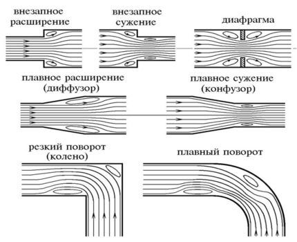
It affects the entire pipeline structure, as well as its individual parts, assemblies - tees, places of significant reduction in pipe diameter, shut-off valves, and various valves. This leads to a loss of pressure in the transported gas.
Hydraulic resistance is always the sum of:
- linear resistance, that is, acting along the entire length of the structure;
- local resistances acting at each component part of the structure where the gas transportation speed changes.
The listed parameters constantly and significantly influence the performance characteristics of each gas pipeline. Therefore, as a result of incorrect calculations, additional and significant financial losses will occur due to the fact that the project will have to be redone.
Rules for performing calculations
It was stated above that the procedure for any hydraulic calculation is regulated by the profile Code of Rules with the number 42-101–2003.
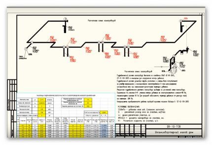
The document indicates that the main way to perform the calculation is to use a computer for this purpose with special programs that allow you to calculate the planned pressure loss between sections of the future gas pipeline or the required pipe diameter.
If there are no such programs or a person believes that their use is inappropriate, then other methods permitted by the Code of Rules can be used.
Which include:
- calculation using the formulas given in the SP is the most complex method of calculation;
- calculation using so-called nomograms is a simpler option than using formulas, because you don’t have to make any calculations, because the necessary data is indicated in a special table and given in the Code of Rules, and you just need to select them.
Any of the calculation methods leads to the same results. Therefore, the newly built gas pipeline will be able to ensure timely, uninterrupted supply of the planned amount of fuel even during the hours of its maximum use.
PC computing option
Performing calculus using a computer is the least labor-intensive - all that is required of a person is to insert the necessary data into the appropriate columns.
Therefore, hydraulic calculations are done in a few minutes, and this operation does not require a large amount of knowledge, which is necessary when using formulas.
To perform it correctly, it is necessary to take the following data from the technical specifications:
- gas density;
- coefficient of kinetic viscosity;
- gas temperature in your region.
The necessary technical conditions are obtained from the city gas department of the locality in which the gas pipeline will be built.Actually, the design of any pipeline begins with the receipt of this document, because it contains all the basic requirements for its design.
Next, the developer needs to find out the gas consumption for each device that is planned to be connected to the gas pipeline. For example, if fuel will be transported to a private house, then stoves for cooking, all kinds of heating boilers are most often used there, and their passports always contain the necessary numbers.
In addition, you will need to know the number of burners for each stove that will be connected to the pipe.
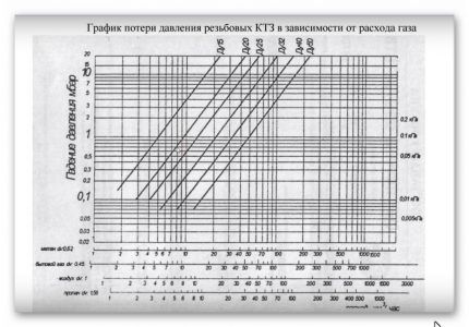
At the next stage of collecting the necessary data, information is selected about the pressure drop at the installation sites of any equipment - this could be a meter, a shut-off valve, a thermal shut-off valve, a filter, or other elements.
In this case, it is easy to find the necessary numbers - they are contained in a special table attached to the passport of each product. The designer should note that the pressure drop at maximum gas consumption must be specified.
At the next stage, it is recommended to find out what the blue fuel pressure will be at the insertion point. Such information may contain the technical conditions of your city gas, a previously drawn up diagram of the future gas pipeline.
If the network consists of several sections, then they must be numbered and the actual length indicated.In addition, for each one, all variable indicators should be written down separately - this is the total flow rate of any device that will be used, pressure drop, and other values.
A simultaneity coefficient will be required. It takes into account the possibility of joint work of all gas consumers connected to the network. For example, all heating equipment located in an apartment building or private house.
Such data is used by a hydraulic calculation program to determine the maximum load on any section or entire gas pipeline.
For each individual apartment or house, the specified coefficient does not need to be calculated, since its values are known and indicated in the table below:
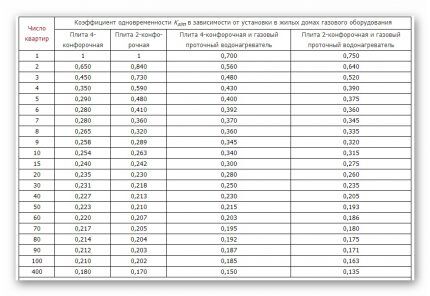
If at some facility it is planned to use more than two heating boilers, furnaces, and storage tank water heaters, then the simultaneity indicator will always be 0.85. This is what you will need to indicate in the corresponding column used for the calculation of the program.
Next you should indicate pipe diameter, and you will also need their roughness coefficients, which will be used in the construction of the pipeline. These values are standard and can be easily found in the Rulebook.
Influence of pipe material on calculation
For the construction of gas pipelines, you can use pipes made only from certain materials: steel, polyethylene. In some cases, copper products are used. Will be widely used soon metal-plastic structures.
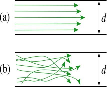
Today, the necessary information can only be obtained for steel and polyethylene pipes. As a result, design and hydraulic calculations can only be carried out taking into account their characteristics, which is required by the relevant Code of Practice. The document also contains the data necessary for the calculation.
The roughness coefficient is always equal to the following values:
- for all polyethylene pipes, regardless of whether they are new or not, - 0.007 cm;
- for already used steel products - 0.1 cm;
- for new steel structures - 0.01 cm.
For any other types of pipes this indicator is not indicated in the Code of Practice. Therefore, they should not be used for the construction of a new gas pipeline, since Gorgaz specialists may require adjustments to be made. And these are again additional costs.
Calculation of flow in a limited area
If the gas pipeline consists of separate sections, then the calculation of the total flow rate for each of them will have to be performed separately. But this is not difficult, since the calculations will require already known numbers.
Defining data using the program
Knowing the initial indicators, having access to the simultaneity table and technical data sheets of stoves and boilers, you can begin the calculation.
To do this, perform the following steps (the example is given for a low-pressure intra-house gas pipeline):
- The number of boilers is multiplied by the productivity of each of them.
- The resulting value is multiplied by the simultaneity coefficient specified using a special table for this type of consumer.
- The number of stoves intended for cooking is multiplied by the productivity of each of them.
- The value obtained after the previous operation is multiplied by the simultaneity coefficient taken from a special table.
- The resulting amounts for boilers and stoves are summed up.
Similar manipulations are carried out for all sections of the gas pipeline. The obtained data is entered into the appropriate columns of the program with which the calculations are performed. The electronics does everything else itself.
Calculation using formulas
This type of hydraulic calculation is similar to that described above, that is, the same data will be required, but the procedure will be lengthy. Since everything will have to be done manually, in addition, the designer will need to carry out a number of intermediate operations in order to use the obtained values for the final calculation.
You will also have to devote quite a lot of time to understand many concepts and issues that a person does not encounter when using a special program. The validity of the above can be verified by familiarizing yourself with the formulas to be used.
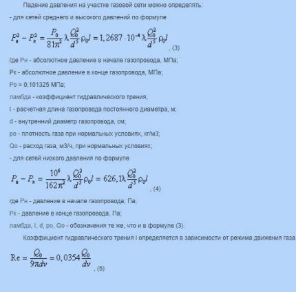
In the application of formulas, as in the case of hydraulic calculations using a special program, there are features for gas pipelines of low, medium and, of course, high pressure. And it’s worth remembering, since a mistake is always fraught with significant financial costs.
Calculations using nomograms
Any special nomogram is a table that shows a number of values, by studying which you can obtain the desired indicators without performing calculations. In the case of hydraulic calculations, the diameter of the pipe and the thickness of its walls.
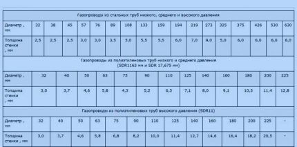
There are separate nomograms for polyethylene and steel products. When calculating them, standard data were used, for example, the roughness of the internal walls. Therefore, you don’t have to worry about the correctness of the information.
Calculation example
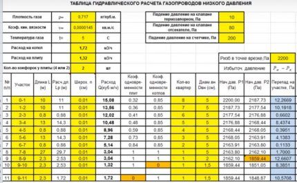
An example of performing hydraulic calculations using a program for low-pressure gas pipelines is given. In the proposed table, all the data that the designer must enter independently is highlighted in yellow.
These are listed in the paragraph on computer hydraulic calculations above. These are gas temperature, kinetic viscosity coefficient, and density.
In this case, calculations are carried out for boilers and stoves; therefore, it is necessary to specify the exact number of burners, which can be 2 or 4. Accuracy is important, because the program will automatically select the simultaneity coefficient.
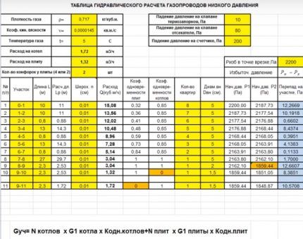
It is worth paying attention to the numbering of sections - they are not invented independently, but are taken from a previously drawn up diagram, where similar numbers are indicated.
Next, the actual length of the gas pipeline and the so-called calculated length, which is longer, are written down. This happens because in all areas where there is local resistance, it is necessary to increase the length by 5-10%. This is done in order to prevent insufficient gas pressure among consumers. The program performs the calculations independently.
The total consumption in cubic meters, for which a separate column is provided, at each site is calculated in advance. If the building is multi-apartment, then you need to indicate the number of housing, starting from the maximum value, as can be seen in the corresponding column.
It is mandatory to enter into the table all elements of the gas pipeline, during the passage of which pressure is lost. The example shows a thermal shut-off valve, a shut-off valve and a meter. The value of the loss in each case was taken from the product passport.

The internal diameter of the pipe is indicated according to the technical specifications, if the gas company has any requirements, or from a previously drawn up diagram. In this case, in most areas it is prescribed at a size of 5 cm, because most of the gas pipeline runs along the facade, and the local city gas requires that the diameter be no less.
If you even superficially familiarize yourself with the given example of performing a hydraulic calculation, it is easy to notice that, in addition to the values entered by a person, there are a large number of others. This is all the result of the program, since after entering the numbers in the specific columns highlighted in yellow, the calculation work is completed for the person.
That is, the calculation itself occurs quite quickly, after which the received data can be sent for approval to the city gas department of your city.
Conclusions and useful video on the topic
This video makes it possible to understand where hydraulic calculations begin and where designers get the necessary data:
The following video shows an example of one type of computer calculation:
Below you can see an example of a calculation using a computer program:
To perform a hydraulic calculation using a computer, as the profile Code of Rules allows, it is enough to spend a little time familiarizing yourself with the program and collecting the necessary data.
But all this has no practical significance, since drawing up a project is a much more extensive procedure and includes many other issues. In view of this, most citizens will have to seek help from specialists.
Do you have any questions, find any shortcomings, or can you add valuable information to our material? Leave your comments, ask questions, share your experience in the block below.


Where can I download this table for the hydraulic calculation of low-pressure gas pipelines? I will be grateful for your answer.