Do-it-yourself grounding in a private house 220V: arrangement of a grounding loop, procedure for installation work
Are you planning to organize 220V grounding in a private house with your own hands or still doubt the need for such an event? Agree that no one wants to become a victim of electric shock. This is exactly what will happen if you ignore basic safety rules.
Grounding is necessary in any residential building: built for permanent residence or serving as shelter from the rain while visiting a dacha. There is even a separate part of the PUE dedicated to this. Chapter 1.7 states that all electrical networks and any electrical equipment must be grounded.
However, the grounding system will perform its function only if its diagram is correct and all components are installed in accordance with the rules. In this article, we reviewed the basic diagrams, compiled lists of requirements, and provided a step-by-step algorithm of actions during installation work.
The content of the article:
Why is grounding needed?
Grounding is the connection of electrical equipment, installation or network point with a grounding device located outside the residential building.
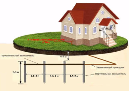
The goals, in addition to ensuring human safety, are: extending the life of household appliances; ensuring stable operation of electrical installations; overvoltage protection.
Grounding also weakens the impact of external electromagnetic radiation and eliminates interference in the network.
Internal and external parts of the system
The grounding system consists of two parts: internal and external. The internal part consists of a PEN bus located in the metering panel and a wire connecting the panel to the external part of the system.
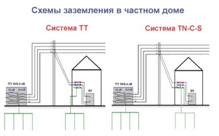
The outer part is ground loop. It consists of electrodes buried in the soil, a metal connection welded to them and a strip connecting the circuit with the wire emanating from the shield.
Basic rules and requirements
The rules and requirements that must be taken into account when organizing grounding in a residential building relate to the materials and sizes of individual elements of the system, and the resistance values of the grounding loop.
There are also standards regarding the placement of the ground loop relative to the surface of the earth and the foundation of a residential building.
Geometric parameters of metal elements
The choice of standard sizes of metal blanks for the manufacture of a grounding device is based on the need to achieve the desired level of resistance.
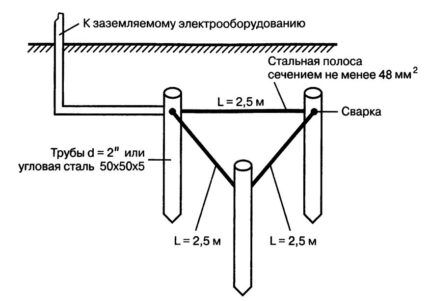
They can be different, but there are restrictions on the minimum values.
These values include:
- The thickness of the sides of the corners used as pins. It should not be less than 4 mm.
- Pipe wall thickness starting from 3.5 mm.
- Cross-section of the connecting strip located between the pins.
The minimum value of the last parameter cannot be less than 48 square meters. mm. Only in this case will the strip perform its function.
Ground loop resistance standards
Compliance with the standards required for the level ground loop resistance, is the main condition for the effectiveness of the entire system.

The following rule works here: the lower the resistance level of the grounding device, the higher the efficiency of the system, the safer it is to stay in the house and use electrical appliances.
Standards for placement of grounding structures
The optimal option for placing structures is a range of 2-4 meters from the outer line of the foundation. In this case, the minimum possible distance is 1 meter, the maximum is 10 meters.
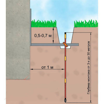
The distance between the surface of the earth and the upper parts of the structure should be 50-70 cm. The ground electrodes themselves are driven to a depth of 3 meters.
It is also worth paying attention to the humidity of the selected plot of land: the moister the soil at the location, the better. Areas planned for tiling or asphalt. The soil under them does not dry out, creating good protection for the entire structure.
Basic options for grounding loops
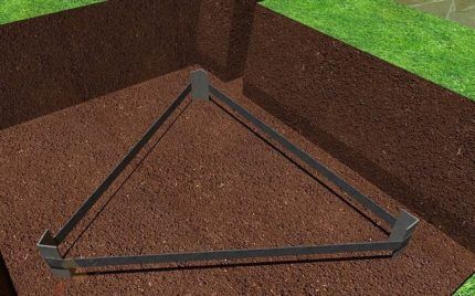
There are several types of grounding loops: modular-pin, linear, closed. The closed one is most often performed in the shape of a triangle.
Option No. 1 - closed loop
In this case, the electrodes are placed at the vertices of an equilateral triangle and connected to each other by metal strips.
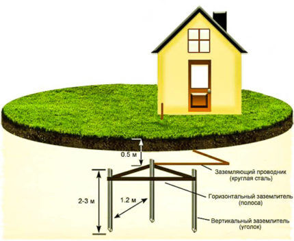
The triangle shape was not chosen by chance: it ensures a closed circuit with the minimum possible number of electrodes. Experts also allow other forms.
For example, a rectangle or a polygon. But they are not economical, as they require the use of more material.
Option No. 2 - linear view and its characteristics
When choosing a linear scheme, the buried electrodes are placed in one line or in a small semicircle. Typically, this version is suitable for small areas where it is not possible to create a closed geometric figure.
The linear circuit has a big drawback: if corrosion or mechanical damage occurs to one of the modules, all sections following it are disabled. In this case, the system is deprived of the ability to fully perform the abductor function.
Option No. 3 - modular-pin type of circuit
The modular-pin circuit is implemented using a prefabricated structure that allows you to assemble an electrode of the required length.
The set consists of round rods with a diameter from 16 to 20-25 mm, a length from 1200 to 1500 mm. Some manufacturers produce rods with threaded ends, thanks to which they can be connected using a coupling. Others prefer a trunnion-less coupling.
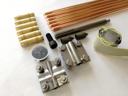
To simplify the penetration process, the kit usually contains impact heads and sharp tips. In addition, as an additional option, it can contain a grounding conductor and a hammer drill attachment.
The procedure for carrying out installation work
To carry out installation work, it is necessary to prepare electrodes from a corner and a metal connection in the form of a steel strip.
If everything is ready, you can start marking. It is necessary to outline not only the future location of the main structure, but also the path along which the external circuit will be connected by a bus to the internal part of the system.
Then you need to:
- Dig a trench 50-70 cm deep along the markings.
- Drive the electrodes to the specified depth.
- Connect the tops of the pins with a metal bond using welding.
- Route the busbar from the outer circuit to metering board.
Next, the effectiveness of the assembled circuit is checked.Since self-installation implies the absence of specialized measuring equipment, you can use simple household methods.

One of these methods is to connect an ordinary incandescent lamp with a power of at least 100 W with one end to ground and the other to phase.
If the installation is done correctly, the lamp will burn as brightly as from a socket. Dim light or its complete absence is a reason to check the build quality.
Common mistakes, tips
When arranging grounding on their own, performers often make a number of typical mistakes. Among them:
- Painting electrodes to prevent corrosion. This is prohibited, as the coating will prevent current from escaping into the soil.
- Connecting electrodes to metal bonding elements using bolts. Only welding is permissible, as it ensures durability and reliability of contact.
- Drilling holes for the pins, eliminating their tight fit to the soil, and thereby reducing the efficiency of the entire system.
To increase the durability of the system and maintain its performance characteristics, it is recommended to treat the metal elements of the ground loop with an anti-corrosion compound.
Particular care should be taken to impregnate welded seams.
Conclusions and useful video on the topic
In the video below, experts demonstrate the entire grounding installation process:
Common mistakes when installing a ground loop:
So, we have become convinced of the need for grounding in a private home, examined the most effective and practical schemes, and compiled a list of materials and the procedure for carrying out the work.
If you have any questions or are ready to share your work, experience, or advice with other users, use our communication form. In it you can place a comment, photo or diagram of your own design. You can also get specialist advice from us. Use it!


Hello. I am planning modular pin grounding for a new wooden house. The house stands in the tundra, on 36 piles of pipes filled with concrete and connected to each other by a channel. Piles with a depth of 2.5 meters, pipe diameter 180 mm. Can I use piles as grounding? If not, do they also need to be grounded after installing the modular-pin grounding?