How to connect an internet outlet: step-by-step installation guide
Do you need to install a special socket for connecting the Internet, but you don’t want to call a technician? Agree that self-installation will save money, and you will be confident in the quality of the work performed.
But you don’t know how to connect an Internet outlet and what is required for this? We will tell you where to start - this article will explain in detail to the home craftsman and construction engineer the connection features, and will also give comprehensive answers to all related questions.
Visual photos and useful videos will help you understand the installation process and tell you what you need to focus on when connecting RJ-45 socket connectors.
The content of the article:
The need to install an outlet
Most of us live in multi-room apartments and private houses. For each individual room of such dwellings, it is necessary to solve one small but rather “insidious” problem: in any available way, create a “point” for connecting devices of different types to the Internet.
It would seem that the answer is obvious - buy and install a Wi-Fi router and there are no problems. But some people, to put it mildly, are not happy about the negative impact of electromagnetic waves from medium- and low-power generators on their own health, the health of their loved ones and especially young children.
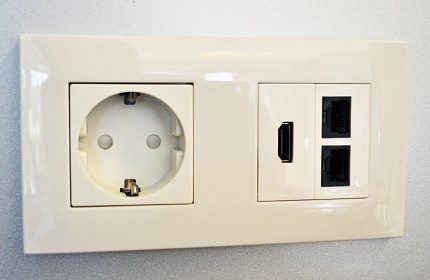
Therefore, it is worth thinking about reducing electromagnetic “smog” in our houses and apartments.
One of these methods is to install Internet sockets directly in the walls of the room.
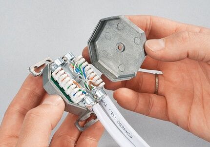
You must understand that this is only one of the options for providing multipoint Internet access for laptops, desktop computers, mini-servers and personal data storage in a home/apartment/office.
The process of connecting an outlet with your own hands is given in the form of step-by-step photo instructions below.
Application options for Internet sockets
In addition to “home” use projects, there are still a sufficient number of options.
In which the installation of such sockets for the Internet will not only be relevant, but sometimes simply an original way out of a special, security-demanding situation, taking into account the technical conditions for providing access to the Internet.
Depending on the type and purpose of the building, technical requirements are put forward for the arrangement of apartments in such buildings.
There are several main categories of such premises:
- offices, classrooms and server rooms;
- Internet clubs and electronic libraries;
- IT stores and computer equipment maintenance workshops;
- structures with increased protection against penetration.
For most offices and classrooms, in addition to having wireless Internet access points, it is mandatory to equip the walls and office furniture with RJ-45 sockets, which ensure the connection of “working” computer stations to the Internet, as well as to local networks.
Not a single server-type room can do without twisted pair connectors installed in/on the walls.This is a mandatory requirement of every IT engineer who has undertaken the construction of a “server room” or data warehouse.
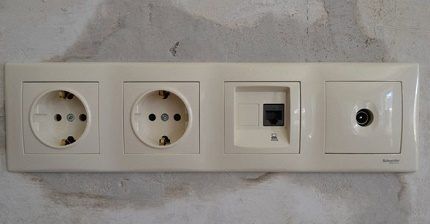
The rapid development of technology affects all aspects of our lives and in particular education.
Now it is very “hard” to imagine an educational institution of any level, from school to university, without the presence of auxiliary search tools (computers). Who search and provide the necessary information in a huge “knowledge bank” - an electronic library.
If you are a private entrepreneur or the owner of a business that is involved in the sale and/or repair of computer and office equipment, then the presence of socket structures is simply “vital” for the normal working conditions of your employees.
And another example of mandatory equipment with Internet sockets and structures is premises for corporate and government security services.
As well as banking and other storage facilities, with increased protection against penetration, where any significant electromagnetic radiation is actually prohibited or interception of packet information via wireless data transmission is possible.
Types and types of Internet outlets
To understand what type of sockets we need to use in this or that case, we need to understand the general classification of sockets for the RJ-45 connector.
But first, RJ-45 is a unified standard for physically connecting computers and network switches using standard 8-conductor shielded wire, often called “twisted pair.”
Because by making a cross section of the cable, you can easily see 4 intertwined pairs of wires. This type of wire is used to build the vast majority of information transmission channels in local and public networks.
You may also be interested in information about types of internet cable and recommendations for selection.
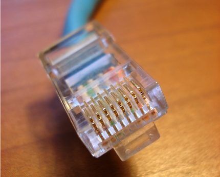
Experts suggest the following classification of sockets:
- By the number of connectors. There are single, double and terminal sockets with 4-8 connectors. In addition, there is also a separate type of combined sockets. Such modules may contain additional types of interfaces, including audio, USB, HDMI, and RJ-45 itself.
- By data transfer rate. There are many varieties and categories, the main ones being category 3 - data transfer speeds up to 100 Mbit/s, category 5e - up to 1000 Mbit/s and category 6 - up to 10 Gbit/s over a distance of up to 55 meters.
- According to the principle of fastening. By analogy with power electrical installation products, there are internal and overhead computer sockets. For an internal socket, the mechanism (contact group of terminals) is recessed into the wall, while for an external socket it is laid along the surface of the wall.
For a socket with hidden wiring laid in the wall, it is necessary to have a protective plastic “cup” in the wall where the terminal block is attached. An external socket is usually mounted using an overhead panel on the wall surface.
As for manufacturers: there are many of them, domestic and foreign. Recently, “Chinese” companies producing network equipment have begun to “even out” in terms of the quality of finished products relative to others.
The products are clearly distinguished by their high quality from such world brands as Digitus, Legrand, VIKO, etc.
It is worth mentioning separately about “keystones”.
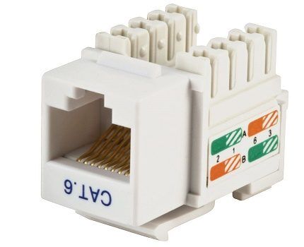
This is a modular architecture for placing individual “stones” - modular connectors for a variety of audio, video, telephone, optical, Mini-DIN and other interfaces, including RJ-45 on one standard panel of the socket block.
This is a fairly flexible and scalable system for providing interfaces to the end user.
Laying "twisted pair" in/on walls
Let's move from theory to practice. If we are talking about laying cables and wires in a new building, then no special questions should arise: we put the twisted pair next to the rest of the communications, usually in corrugated tubes, and them in the cut-out hollows.
It is imperative to remember the number of wires inserted into the channel and their average diameter, and also take into account the channel diameter + 25% of the total sum of all cable diameters.
It’s another matter if we are renovating an existing room and creating new channels. It is necessary to take into account the material from which the walls are made: frame gypsum panels, brick, concrete, etc.
The hardest thing is to make channels in concrete/brick without damaging other communications.
To detect wiring in walls, you can use any available building electromagnetic wiring detectors.
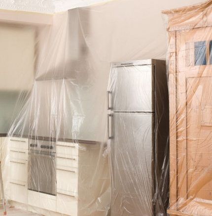
It should be noted that there will be a lot of dust if you work in concrete. As a result of gating, abrasive dust and small pebbles will cover everything in the room: walls, ceiling, floor, furniture, equipment.
Therefore, you need to initially vacate the room or cover everything with plastic film.
We strongly recommend that the master wear the following set:
- tight jumpsuit (jacket/pants);
- headdress (you can wear a swimming cap or bandana);
- glasses (we recommend ski or other ones with protection for the temporal areas of the face);
- thin and comfortable gloves, boots, personal respiratory protection equipment (protective masks, respirators, bandages, etc.).
To create grooves (forming channels in foam concrete or brick walls), you need to use the following tools: wall chasers, wall chasers, furrow makers.
As an option, it is still possible to use powerful “grinders” with cutting discs (diamond-coated). The cutting depth of the channel should be 30-35 mm, the width up to 25 mm exclusively for one or more twisted pair wires.
Absolutely all channels and gutters must be made at right angles - this is a mandatory rule for any construction repair.
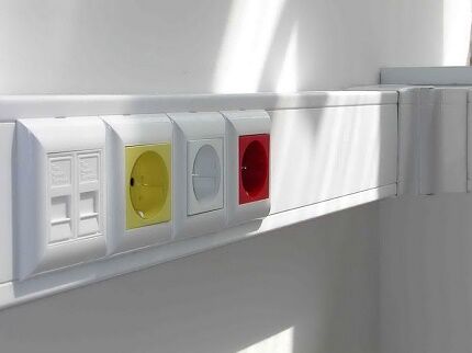
As for cavities for sockets, they are made using a bolt, an electric hammer or a drill/hammer with a socket attachment.
But initially, you need to determine the approximate placement of Internet outlets in the premises. As a rule, holes for RJ45 sockets are drilled at a height of 1000-1200 mm from the floor or 150-300 mm.
For residential premises, one or two sockets on opposite walls of the room are sufficient. For offices, they usually place one outlet near the future workplace.
In server rooms and rooms with similar functions, a different strategy is used - make 3-4 holes for modular socket blocks, two blocks on one wall and one on all other walls.
And the last thing you need to pay attention to regarding the laying of wires is that sometimes it is possible to lay communications under the floor or in the ceiling of the room.
In such a situation, the question of gating the walls does not arise; it is enough to run the wire under the floor or into the ceiling and bring it out in the area of the socket hole on the wall.
Features of RJ-45 cable pinout
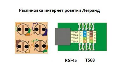
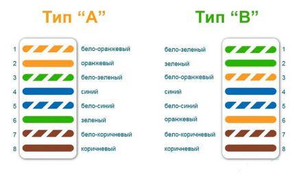
Before connecting Internet sockets, you need to clearly know and understand where and what color to mount each individual twisted pair wire. To do this you need to know the crimping scheme and rules DIY RJ-45 cable crimping.
There are two main types RJ-45 wire pinouts: straight and cross. The first type of cable is used to connect end devices (computer/PC, smart TV/Smart TV, switch/Switch) to the so-called router.
The second type of cable is used to connect devices with similar functions (computer - computer, router - router, switch - switch) to each other.
First, we leave about 100-150 mm from the plane of the wall along the length of the cable, and cut off the rest of the cable. This length will be sufficient for possible subsequent rewiring of the wiring.
Before starting electrical installation work, you can familiarize yourself with twisted pair crimping circuits for 8 and 4 cores, discussed in our other article.
Now you need to free 4 pairs of wires from the outer sheath and from the foil (it acts as protective shielding), if any.
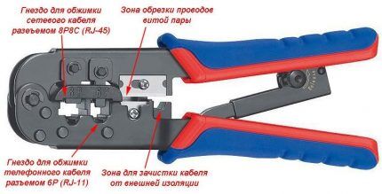
Inside the twisted pair there is also a special thread with which you can easily release all the necessary wiring.You can also use a regular knife or a special cutting surface, which is equipped with almost all crimping pliers.
At the next stage, we straighten all twisted pairs of multi-colored wires and carefully “seat” each individual color into its niche according to the color pinout in the socket terminal block.
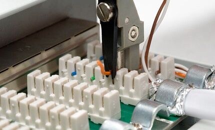
This must be done in such a way that the rest of the wire with “untouched” insulation falls under the fixing clamp of the terminal block. Now we tighten the fixing bolts with a screwdriver on the terminal block and at the same time press the remaining wires so that they do not come out of their seats.
Finally, with a “feeling of strength,” we recess the clamping connectors on the terminal block with a screwdriver and separately secure each core in the terminal group, while cutting through the braid of small wires. Then we cut off the remains. The wiring must all be located at the same height from the base of the terminal block.
You may also find information about ways to extend twisted pair.
Checking Wiring Signals
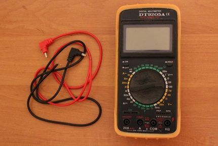
It is worth mentioning separately the possibility of checking the presence, and most importantly the correctness, of signals passing through the 8 cores of a twisted pair cable. This can be done using a regular electrical tester.
But first you need to have a patch cord (ready-to-use wires at both ends of which are mounted, again according to a direct pinout pattern, RJ-45 connectors) and a second unmounted Internet socket or keystone.
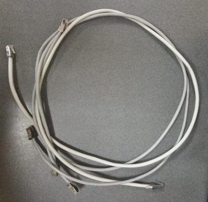
We first mount the second end of the laid wire into an unmounted socket/keystone, into which we insert one end of the patch cord.
We switch the tester to the sound signal mode and compare the corresponding channels of the connectors on the patch cord and in the Internet outlet. We receive a sound signal that indicates the presence of a connection.
There is also the option of checking signals using special cable testers, but this requires another ready-made patch cord that works in a direct manner. We insert one end of each patch into sockets (new and temporary), and insert the other two into the tester cable.
Light and sound on the tester panel indicate the presence or absence of a signal on a particular twisted pair core. We look and check the signal.
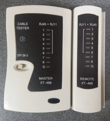
Ideally, we will receive 8 light and sound signals in sequence on the cable tester. In these two ways, you can check the correctness of the pinout and the presence of a full signal for data transmission via twisted pair.
Installation of the terminal block and mounting of the cover plate
After checking the signals, we move on to the final part of installing the Internet outlet.
To do this, carefully hide the rest of the wires and return the terminal block with the connected conductors back to the socket of the socket, tighten it with the fixing bolts to the built-in “glass”.
The terminal block should “sit” tightly in the socket, there should be no protruding or kinked wires.
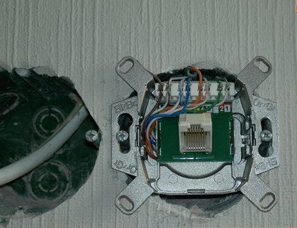
Once again, we check that the connection is correct; to do this, we connect a device, for example, a laptop, and see if it detects a connected local network or the Internet.
If there is no connection on the device, we return to the pinout point and re-check the correctness of the actions performed, as well as the quality of the compression. It often happens that one of the cables is simply not sufficiently pressed into the terminal block. To do this, you just need to recess the core clamp more tightly.
After an additional check of the network’s functionality, we trim off all remaining protruding wires and proceed to installing the cover plate. The cover is usually equipped with several plastic latches.
It is enough to accurately place it on the socket of the socket and press until you hear a clicking sound. That's it, the Internet socket is installed and ready for use.
Conclusions and useful video on the topic
Similar instructions can be used for connecting and installing any types of Internet outlets:
They may differ in the location of contact groups and the set of interfaces, the mounting method, but this does not change the essence of the matter at all:
Connecting single or modular Internet sockets with your own hands is possible for any home craftsman, not to mention IT engineers. The main thing is to “guess” the color pinout of the cores the first time and get a high-quality data transmission signal via twisted pair.
Have you repeatedly performed electrical installation work and can supplement the information in our article with practical recommendations? Or did you install such an outlet with your own hands and encounter an interesting point that we did not mention here? Please share your tips with our readers - leave comments below this article.


At home I laid out the Internet cable from the router to two desktop computers in different rooms.
The article describes the process in great detail, and at first glance it may seem that it is very difficult to do. In fact, there is nothing difficult about it. Buy twisted pair cable of the required length and crimping pliers, also do not forget about the required number of plugs. I recommend purchasing plugs with a reserve, since without experience, you will not be able to crimp properly the first 2-3 times.
I took an overhead socket so as not to drill into the wall. Laying the cable and installing the socket does not cause any difficulties; all the wisdom lies in the correct and high-quality crimping of the cable into the plug.
When connecting computers to the router, I used the pinout diagram according to type A. Well, look carefully at the colors of the wires, since the cable has striped wires of the same color and wires of the same color without stripes, it is important not to confuse them. And then it’s just sleight of hand.
Good day! I would like to add a little to your instructions and remind you of a couple more important points that seem to me.
It is advisable that the total length of the cable from the provider’s equipment to your device in the apartment does not exceed 100 meters, since if the footage exceeds 100+, the signal is partially weakened.
It is also important to choose the right cable.If you are installing it in the wall, it is better to take a cable with a copper core. It will last longer and transmit the signal better.
Is Wi-Fi radiation really so harmful that it’s worth running a wire throughout your entire apartment? I don’t know, I personally use a router, reduced the power of its transmitter to 20% of the total power, and it works fine.
Generally speaking, it’s strange to hear about the dangers of wi-fi when we are constantly in this environment - any cafe, neighbors behind the wall, and even some buses have it. As they say, you can’t hide far. But if you really want a wire, then I would choose the cable channel method - less labor-intensive and cheaper.
Yes, now there is no escape from wi-fi networks and it’s really stupid to run a cable through the entire apartment. But all sorts of cases happen. For example, you can take care of such sockets in advance during repairs, when laying the main wiring. It will be quite convenient later.
Well, or even professional gamers need a cord to reduce the ping :)
Perhaps I’m wrong, but the first to appear was the “cross” pinout, which you listed as type “B”. To connect computers directly, even before the advent of local networks, the Internet, routers, routers, etc. And it was designated as type “A”. I came across the installation of ABB Basic computer sockets. You have me confused. Is there a diagram?
As stated in the comments above, copper cable is more reliable. I install video surveillance systems using twisted pair cables (PoE). If the cable is not copper, when the line length is more than 60-70 meters, IP cameras experience signal loss. Copper holds 100 m. You can check by stripping the core and scraping it with a knife. If it turns white, it’s copper-plated. The price difference is 20-40 rubles/m.
Regarding Wi-Fi. If you have a two-story cottage or three-ruble ruble in a monolithic (panel) house, will a router with three powerful antennas save you? And imagine how it emits radiation in addition to the electromagnetic radiation from the electrical wiring. In addition, a new IPBaseT (HDBaseT) protocol has been developed for transmitting 4K video over twisted pair cables, and not over 4 HDMI cables as it is now. 8K in the future. All 4 pairs (8 cores) are used, not 2 as now.
The cable can be laid in a plinth with a cable channel. Or under the ceiling plinth. When crimping an RJ-45 connector, you must carefully straighten all the wires and cut them evenly. I install systems using shielded cable (FTP, not UTP). It is not always possible to run local networks separately from power cables (especially in office cable ducts) and cross them at right angles.
As for the pinout of the RJ45 connector by color, everything is quite simple; here the author did not touch on the background, since it simply will not be interesting to many who are not initiated into the topic.
Regarding connecting IP cameras - I agree with you here, only copper cable. Copper is more practical, more durable and less susceptible to mechanical damage when bending and twisting.
Regarding routers for two- and three-story houses, it would be more practical to make 2-3 routers on each floor than to install one powerful one.
As for laying network cables separately from wiring and power cables - yes, this is ideal, but in practice it is not always possible to adhere to this rule. To avoid additional stress on the cable from bending at right angles, I make round twists.
Good day to all.I installed an Internet socket at home according to diagram “B” and I want to connect a router to it. Please tell me how to crimp both ends of a twisted pair cable between the socket and the router?
How to connect 8 cables?
There is an internet socket with two inputs. I attached the diagram. I connected one according to the first circuit “B” with 4 wires, the second according to the second. Question: how to connect to 2 connectors on the other side? Thank you