How to test a capacitor with a multimeter: rules and features of measurements
Capacitors are present in various technologies. They are also often the cause of malfunctions.To quickly identify a faulty element and replace it, you need to know how to test a capacitor with a multimeter, since this is the easiest way.
We will tell you how to use an inexpensive but functional device to identify faulty elements. In the article we presented, the types of capacitors and the procedure for checking them are discussed. Taking into account our advice, you can easily find the “weak link” in the electrical circuit.
The content of the article:
What is a capacitor and why is it needed?
The industry produces capacitors of many different types, used in many industries. They are needed in automobile and mechanical engineering, radio engineering and electronics, instrument making and the production of household appliances.
Capacitors are a kind of “storage” of energy, which they release when short-term power failures occur. In addition, a certain type of these elements filters out useful signals and assigns the frequency of devices generating signals. The discharge-charge cycle of a capacitor is very fast.
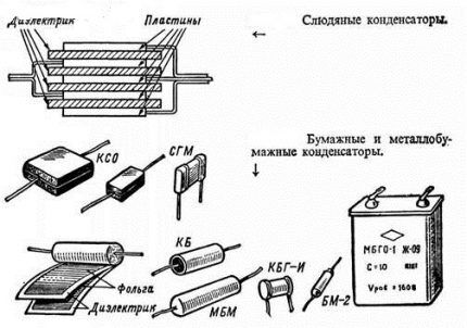
In a circuit with alternating current, the capacitor plates are alternately recharged at the frequency of the flowing current. This is explained by the fact that the voltage changes periodically at the terminals of the source of such current. The result of such transformations is alternating current in the circuit.
Just like a resistor and a coil, a capacitor exhibits resistance to alternating current, but it is different for currents of different frequencies. For example, while transmitting high-frequency currents well, it can at the same time almost act as an insulator for low-frequency currents.
The resistance of a capacitor is related to its capacitance and the frequency of the current. The larger the last two parameters, the lower its capacitance.
Polar and non-polar varieties
Among the huge number of capacitors, there are two main types: polar (electrolytic), non-polar. Paper, glass, and air are used as dielectrics in these devices.
Features of polar capacitors
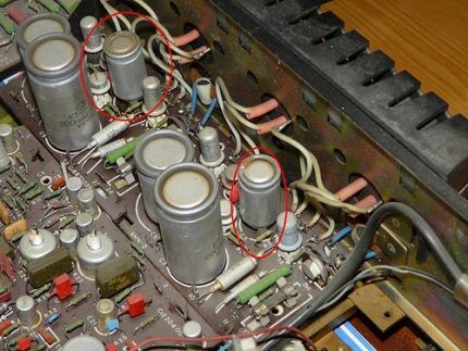
The name “polar” speaks for itself - they have polarity and are electrolytic. When including them in the scheme, it is necessary to strictly follow it - strictly “+” to “+”, and “-” to “-”. If you ignore this rule, the element not only will not work, but may even explode. Electrolyte can be liquid or solid.
The dielectric here is paper impregnated with electrolyte. The capacity of the elements ranges from 0.1 to 100 thousand microfarads.
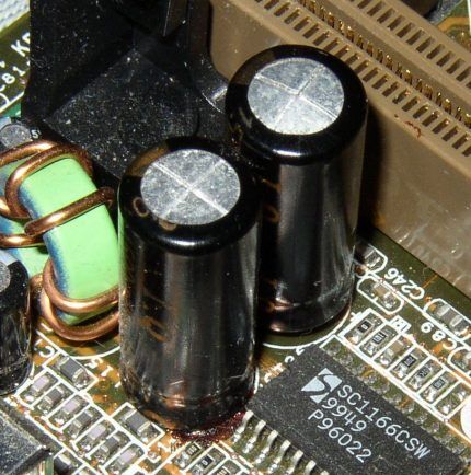
When the plates short, heat is released. Under its influence, the electrolyte evaporates and an explosion occurs.
Modern capacitors have a small indentation and a cross on top. The thickness of the depressed area is less than the rest of the cover surface. When it explodes, its upper part opens up like a rose. For this reason, swelling can be observed at the ends of the body of the faulty element.
Differences between non-polar capacitors
Non-polar film elements have a dielectric in the form of glass or ceramics. Compared to electrolytic capacitors, they have less self-charge (leakage current). This is explained by the fact that ceramics have a higher resistance than paper.
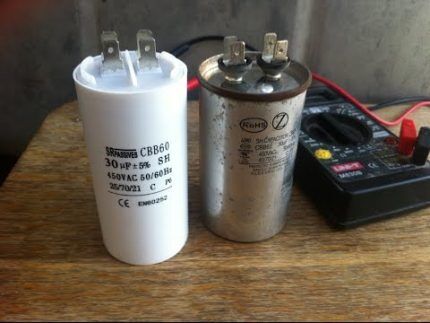
All capacitors are divided into general purpose and special parts, which are:
- High voltage. Used in high-voltage devices. They are produced in various designs. There are ceramic, film, oil, and vacuum high-voltage capacitors. They differ significantly from ordinary parts and access to them is limited.
- Launchers. Used in electric motors to ensure their reliable operation. They increase the starting torque of the engine, for example, pumping station or compressor at startup.
- Impulse. Designed to create a strong voltage surge and transmit it to the receiving panel of the device.
- Dosimetric. Designed for operation in circuits where the level of current loads is low. They have very low self-discharge and high insulation resistance. Most often these are fluoroplastic elements.
- Interference suppressing. They soften the electromagnetic background in a large frequency fork.They are characterized by insignificant self-inductance, which makes it possible to raise the resonant frequency and expand the band of restrained frequencies.
In percentage terms, the largest number of parts failing to function occurs in cases where voltage exceeding the standard voltage is applied. Design errors can also cause malfunctions.
If the dielectric changes its properties, the capacitor also malfunctions. This happens when it leaks, dries out, and cracks. The capacity immediately changes. It can only be measured using measuring instruments.
How to check with a multimeter
Checking capacitors multimeter It is better to do this by removing them from the electrical circuit. This way you can provide more accurate indicators.
The main property of all capacitors is the passage of current of an exclusively variable nature. The capacitor passes direct current only at the very beginning for a very short time. Its resistance depends on the capacitance.
How to check a polar capacitor?
When checking an element with a multimeter, the following condition must be met: the capacitance must be greater than 0.25 µF.
The technology for measuring a capacitor to identify faults with a multimeter is as follows:
- Take the capacitor by the legs and short-circuit it with some metal object, tweezers, for example, or a screwdriver. This action is necessary in order to discharge the element. The appearance of a spark will indicate that this has happened.
- Set the multimeter switch to continuity testing or measuring resistance indicators.
- Touch the probes to the terminals of the capacitor, taking into account the polarity - a red probe is connected to the positive leg, and a black one to the negative leg. In this case, a direct current is generated, therefore, after a certain period of time, the resistance of the capacitor will become minimal.
While the probes are on the inputs of the capacitor, it is charged, and its resistance continues to increase until it reaches a maximum.
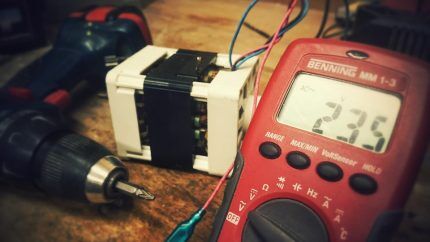
If, upon contact with the probes, the multimeter begins to beep and the needle stops at zero, this indicates a short circuit. This caused the capacitor to malfunction. If the arrow on the dial immediately shows 1, it means that there is an internal break in the capacitor.
Such capacitors are considered faulty and must be replaced. If “1” appears only after a while, the part is working properly.
It is important to carry out measurements so that incorrect behavior does not affect the quality of the measurements. Do not touch the probes with your hands during the process. The human body has very little resistance, and the corresponding leakage rate is many times higher.
The current will follow the path of less resistance, bypassing the capacitor. Consequently, the multimeter will show a result that has nothing to do with the capacitor. You can also discharge a capacitor using an incandescent lamp. In this case, the process will proceed more smoothly.
Such a moment as discharging the capacitor is mandatory, especially if the element is high-voltage.They do this for safety reasons and in order not to damage the multimeter. Residual voltage on the capacitor can damage it.
Inspection of a non-polar capacitor
It is even easier to check non-polar capacitors with a multimeter. First, the measuring limit on the device is set to megaohms. Next they touch with probes. If the resistance is less than 2 MΩ, then the capacitor is most likely faulty.
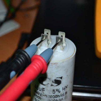
While charging the element with a multimeter, it is possible to check its serviceability if the capacity starts from 0.5 μF. If this parameter is smaller, changes on the device are invisible. If you still need to check an element less than 0.5 μF, then this can be done using a multimeter, but only for a short circuit between the plates.
If it is necessary to examine a non-polar capacitor with a voltage above 400 V, this can be done provided that it is charged from a source protected from short-circuit. circuit breaker. A resistor rated for a resistance of more than 100 Ohms is connected in series with the capacitor. This solution will limit the primary current surge.
There is also a method for determining the performance of a capacitor, such as checking for a spark. At the same time, it is charged to the working value of the capacity, then the terminals are short-circuited with a metal screwdriver having an insulated handle. Performance is judged by the strength of the discharge.
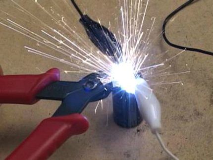
Immediately after charging and after some time, measure the voltage on the legs of the part. It is important that the charge lasts for a long time. Then you need to discharge the capacitor through the resistor through which it was charged.
Capacitor Capacitance Measurement
Capacitance is one of the key characteristics of a capacitor. It must be measured to ensure that the element accumulates and holds a charge well.
To make sure that the element is working, you need to measure this parameter and compare it with the one indicated on the body. Before checking any capacitor for functionality, you need to take into account some of the specifics of this procedure.
If you try to measure using probes, you may not get the desired results. The only thing that can be done is to determine whether this capacitor is working or not. To do this, select the ringing mode and touch the legs with the probes.
When you hear a squeak, swap the probes and the sound should repeat. You can hear it with a capacitance of 0.1 µF. The higher this value, the longer the sound.
If you need accurate results, the best way out in this situation is to use a model that has special contact pads and the ability to adjust the fork to determine the capacitance of the element.
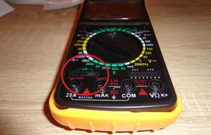
The device is switched to the nominal value indicated on the capacitor body. The latter is inserted into the landing “sockets”, having previously discharged it using a metal object.
The screen should display a capacitance value approximately equal to the nominal value.When this does not happen, it is concluded that the element is damaged. You need to make sure that there is a new battery in the device. This will provide more accurate readings.
Measuring voltage with a multimeter
You can also find out about the performance of a capacitor by measuring the voltage and comparing the result obtained with the nominal value. To perform the test, you will need a power source. Its voltage should be slightly lower than that of the element being tested.
So, if the capacitor has 25 V, then a 9-volt source is sufficient. The probes are connected to the legs, taking into account the polarity, and wait for some time - literally a few seconds.
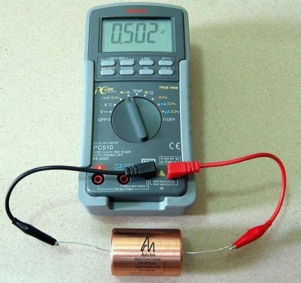
It happens that time has expired, but the expired element is still functional, although its characteristics are different. In this case, it must be constantly monitored.
The multimeter is set to voltage measurement mode and the test is performed. If a value identical to the nominal value appears on the display almost immediately, the element is suitable for further use. Otherwise, the capacitor will have to be replaced.
Checking capacitors without soldering
The capacitors do not need to be unsoldered from the board for testing. The only condition is that the board must be de-energized. After de-energizing, you need to wait a little while for the capacitors to discharge.
It should be understood that it will not be possible to get a 100% result without soldering the element from the board. Parts located nearby interfere with a full check. You can only make sure that there is no breakdown.
In order to check the serviceability of the capacitor without desoldering it, simply touch the terminals of the capacitor with probes to measure the resistance. Based on the type of capacitor, the measurement of this parameter will differ.
Recommendations for testing capacitors
Capacitor parts have one unpleasant property - when soldered after exposure to heat, they are very rarely restored. At the same time, you can qualitatively check the element only by unsoldering it from the circuit. Otherwise, it will be shunted by nearby elements. For this reason, some nuances should be taken into account.
After the tested capacitor is soldered into the circuit, you need to put the device being repaired into operation. This will make it possible to monitor his work. If its performance is restored or it begins to function better, the tested element is replaced with a new one.
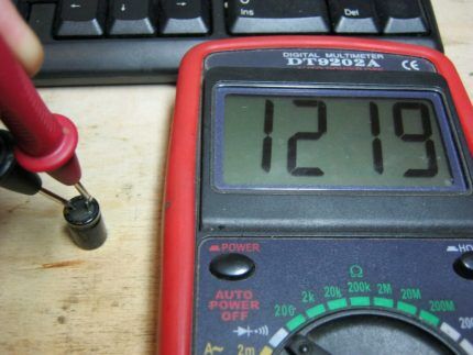
To shorten the test, not two, but only one of the capacitor terminals are unsoldered. You need to know that this option is not suitable for most electrolytic cells, which is due to the design features of the case.
If the circuit is complex and includes a large number of capacitors, the fault is determined by measuring the voltage across them. If the parameter does not meet the requirements, the suspicious element must be removed and checked.
If faults are detected in the circuit, you need to check the release date of the capacitor. The drying out of the element during 5 years of operation is on average about 65%. It is better to replace such a part, even if it is in working order.Otherwise, it will distort the operation of the circuit.
For new generation multimeters, the maximum for measurement is a capacitance of up to 200 μF. If this value is exceeded, the control device may fail, although it is equipped with a fuse. The latest generation equipment contains SMD electrical capacitors. They are very small in size.
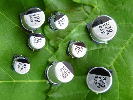
It is very difficult to unsolder one of the terminals of such an element. Here it is better to raise one pin after unsoldering, isolating it from the rest of the circuit, or disconnect both pins.
You can learn how to check the voltage in an outlet with a multimeter from next article, which we highly recommend reading.
Conclusions and useful video on the topic
Video #1. Details on checking a capacitor using a multimeter:
Video #2. Inspection of the capacitor on the board:
There is no point in purchasing complex equipment for diagnosing capacitors. It is quite possible to use a multimeter with the appropriate measurement range for this purpose. The main thing is to be able to correctly use all its capabilities.
Although this is not a highly specialized device and its limits are limited, it is sufficient for examining and repairing a large number of popular radio-electronic devices.
Please write comments in the block below, post photos and ask questions about the topic of the article. Tell us about how you tested the capacitors for functionality. Share useful information that will be useful to site visitors.


Unfortunately, the multimeter only allows you to find capacitors that have already lost the lion's share of their capacity, and does not detect some faults at all. Those who are constantly engaged in “sorting out” electrolytic capacitors should pay attention to a more efficient device - an ESR probe (in the Russian version, ESR is equivalent series resistance).
There are various circuits for assembly, even using a pair of KT315 transistors, but I see no point in discussing them. Nowadays, ready-made Chinese kits are available that can be assembled by a novice radio amateur. The probe allows you to easily find dead capacitors, even without visual signs of a malfunction. By the way, there are probes that allow you to determine the suitability of a capacitor without removing it from the board.
I looked at several sites on the topic “how to test a capacitor.” Everyone has the same thing, even the words are the same, there are no exceptions or details. The question is this: capacitors are 470 microfarads at 16 volts; 33 uF at 50 volts in 200 ohm mode - no change, and in 20 ohm mode - charging. Is it correct or not that is the question? Please explain. (preferably by email)