Ohm's law for a complete chain and for a section of a chain: options for writing the formula, description and explanation
There is no way for a professional electrician or electronics specialist to bypass Ohm’s law in his own activities, solving any problems related to the setup, adjustment, and repair of electronic and electrical circuits.
Actually, everyone needs to understand this law. Because everyone has to deal with electricity in everyday life.
And although the German physicist Ohm’s law is provided for in the secondary school curriculum, in practice it is not always studied in a timely manner. Therefore, in our material we will consider such a relevant topic for life and understand the options for writing the formula.
The content of the article:
Single section and complete electrical circuit
Considering an electrical circuit from the point of view of applying Ohm's law to a circuit, two possible calculation options should be noted: for a separate section and for a full-fledged circuit.
Calculation of the current of an electrical circuit section
A section of an electrical circuit, as a rule, is considered to be the part of the circuit that excludes the source of EMF, as having additional internal resistance.
Therefore, the calculation formula, in this case, looks simple:
I = U/R,
Where, respectively:
- I – current strength;
- U – applied voltage;
- R - resistance.
The interpretation of the formula is simple - the current flowing through a certain section of the circuit is proportional to the voltage applied to it, and the resistance is inversely proportional.

Thus, the formula clearly describes the dependence of the current flow through a separate section of the electrical circuit relative to certain values of voltage and resistance.
The formula is convenient to use, for example, when calculating the parameters of the resistance that needs to be soldered into the circuit if the voltage and current are given.

The above figure will help determine, for example, the current flowing through a 10-ohm resistance to which a voltage of 12 volts is applied. Substituting the values, we find – I = 12 / 10 = 1.2 amperes.
The problems of finding resistance (when the current and voltage are known) or voltage (when the voltage and current are known) are solved in a similar way.
Thus, you can always select the required operating voltage, the required current strength and the optimal resistive element.

By the way, the connecting wires of any circuit are resistances. The amount of load they have to bear is determined by the voltage.
Accordingly, again using Ohm’s law, it becomes possible to accurately select the required conductor cross-section, depending on the core material.
We have detailed instructions on our website cable cross-section calculation in terms of power and current.
Calculation option for a complete chain
A complete circuit is made up of a section (sections), as well as a source of EMF. That is, in fact, the internal resistance of the EMF source is added to the existing resistive component of the circuit section.
Therefore, it is logical to slightly change the above formula:
I = U / (R + r)
Of course, the value of the internal resistance of the EMF in Ohm’s law for a complete electrical circuit can be considered negligible, although this resistance value largely depends on the structure of the EMF source.
However, when calculating complex electronic circuits, electrical circuits with many conductors, the presence of additional resistance is an important factor.

Both for a section of a circuit and for a complete circuit, the natural moment should be taken into account - the use of constant or variable current.
If the points noted above, characteristic of Ohm’s law, were considered from the point of view of using direct current, accordingly with alternating current everything looks somewhat different.
Consideration of the effect of the law on a variable quantity
The concept of “resistance” to the conditions of passing alternating current should be considered more like the concept of “impedance”. This refers to the combination of a resistive load (Ra) and a reactive resistor load (Rr).
Such phenomena are caused by the parameters of inductive elements and the laws of switching in relation to a variable voltage value - a sinusoidal current value.
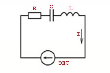
In other words, there is an effect of current values leading (lag) from voltage values, which is accompanied by the appearance of active (resistive) and reactive (inductive or capacitive) powers.
Such phenomena are calculated using the formula:
Z=U/I or Z = R + J * (XL -XC)
Where: Z – impedance; R – active load; XL , XC – inductive and capacitive load; J - coefficient.
Serial and parallel connection of elements
For elements of an electrical circuit (section of a circuit), a characteristic point is a serial or parallel connection.
Accordingly, each type of connection is accompanied by a different pattern of current flow and voltage supply.In this regard, Ohm's law is also applied differently, depending on the option of including elements.
Circuit of series-connected resistive elements
In relation to a series connection (a section of a circuit with two components), the following formulation is used:
- I = I1 = I2 ;
- U = U1 +U2 ;
- R = R1 + R2
This formulation clearly demonstrates that, regardless of the number of resistive components connected in series, the current flowing through a section of the circuit does not change in value.

The magnitude of the voltage applied to the effective resistive components of the circuit is the sum and totals the value of the emf source.
In this case, the voltage on each individual component is equal to: Ux = I * Rx.
The total resistance should be considered the sum of the values of all resistive components in the circuit.
Circuit of parallel connected resistive elements
In the case when there is a parallel connection of resistive components, the following formulation is considered fair in relation to the law of the German physicist Ohm:
- I = I1 +I2 … ;
- U = U1 =U2 … ;
- 1/R = 1/R1 + 1/R2 + …
Options for creating circuit sections of a “mixed” type, when parallel and serial connections are used, are not excluded.

For such options, the calculation is usually carried out by initially calculating the resistive rating of the parallel connection. Then the value of the resistor connected in series is added to the result obtained.
Integral and differential forms of the law
All of the above points with calculations are applicable to conditions when conductors of, so to speak, “homogeneous” structure are used in electrical circuits.
Meanwhile, in practice, one often has to deal with the construction of schematics, where the structure of the conductors changes in different sections. For example, wires of a larger cross-section or, conversely, a smaller one, made from different materials, are used.
To take into account such differences, there is a variation of the so-called “differential-integral Ohm’s law.” For an infinitesimal conductor, the current density level is calculated depending on the voltage and conductivity value.
The following formula is used for differential calculation: J = ό * E
For the integral calculation, accordingly, the formulation is: I * R = φ1 – φ2 + έ
However, these examples are rather closer to the school of higher mathematics and are not actually used in the real practice of a simple electrician.
Conclusions and useful video on the topic
A detailed analysis of Ohm's law in the video below will help to finally consolidate knowledge in this direction.
A unique video lesson qualitatively reinforces the theoretical written presentation:
The work of an electrician or the activity of an electronics engineer is integrally connected with moments when one actually has to observe Georg Ohm’s law in action. These are some kind of truisms that every professional should know.
Extensive knowledge on this issue is not required - it is enough to learn the three main variations of the wording in order to successfully apply it in practice.
Would you like to supplement the above material with valuable comments or express your opinion? Please write comments in the block below the article. If you have any questions, don't hesitate to ask our experts.


