Air conditioner errors Lessar: identifying breakdowns by code and instructions on how to fix problems
Lessar air conditioning systems are practical and safe equipment to use.It is equipped with high-quality protection against voltage surges, temperature increases/decrease, and a self-diagnosis system. In order for the owner to be able to determine malfunctions himself, errors in Lessar air conditioners are displayed on the device display.
We will tell you how breakdowns of the climate control unit are identified by special codes and indicators. We will show you how you can independently determine the malfunction of software, sensors, and other parts and mechanisms. Agree, it is important to identify a problem in the system in a timely manner so that you do not have to buy new equipment.
The article examines common types of errors in various models of split systems of this brand, as well as methods for identifying faults and ways to eliminate them. The presented instructions for eliminating breakdowns and failures in the system will help you assess the complexity of the work and make a decision - to correct the errors yourself or contact a workshop.
The content of the article:
Features of self-diagnosis
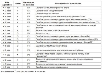
If a breakdown or failure in the electronics is detected, the Lessar climate control unit diagnostic system displays an error code on the front of the indoor unit panel or control panel. The fault code is a letter on the screen and a combination of LEDs that blink in a certain order.
The error indication and alphanumeric code are displayed until the system malfunction is completely corrected.
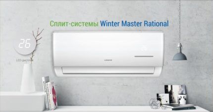
If the split system is not functioning properly, you need to pay attention to the display. An error in the operation of the device is displayed there. Thanks to their presence, the user will be able to independently identify the cause of the malfunction and, if possible, eliminate it. If a complex violation occurs, you will need to contact the service center for help.
To troubleshoot problems yourself, you need to understand in more detail the design features of climate control equipment.
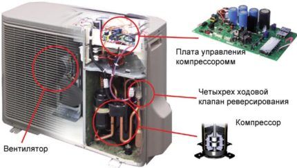
Household (wall-mounted, multi-split systems) and semi-industrial (cassette, floor-ceiling, duct, column type) systems consist of two parts, which are connected to each other by a freon route - an internal and external compressor-condensing unit.
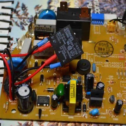
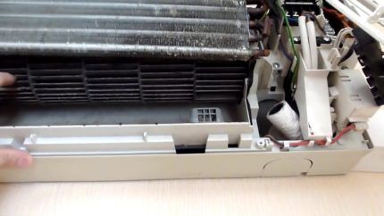
The design of the internal evaporator unit consists of a network cable, a front panel, filter elements, blinds, an evaporator, a fan, a tray for accumulated condensate, and a control board.
The components of the external unit of the split system are: compressor, 4-way valve, condenser temperature sensor, capillary tube, filter, control board, fan. More powerful air conditioners - 36-60 thousand.BTU, - additionally equipped with high and low pressure switches, a muffler, various filters, a battery, and an air temperature sensor.
After familiarizing yourself with the diagram of the air conditioning system, the user will be able to identify the breakdown, replace and even repair the part or mechanism that has failed.
Error codes in household units
Before independently diagnosing errors in Lessar units, you should check the parameters of the input voltage, the value of which should be within the normal range of +/- 10%. You should also make sure that the connection between the external and internal units is correct. If the split system is connected incorrectly, the diagnostic measures taken will not give the correct result.
In household climate control equipment, malfunctions may occur both in the internal part and in the external unit.
#1. Troubleshooting indoor unit
Let's look at common errors that occur when operating units at home, and ways to correct them.
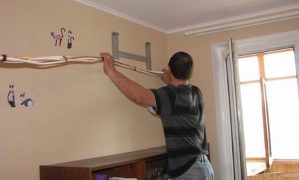
It is not recommended to solve problems with the air conditioning system on your own if a burning smell appears. You should not try to repair it yourself if the internal electrical circuit breaker frequently trips, the cable or socket to which the unit is connected heats up, unusual noises and creaks occur, or water gets inside the room.
In all of the above cases, you should immediately disconnect the device from the power supply and contact the service center for help.
Internal volatile memory (EEPROM software) error – E0, the indicator lights up 1 time.
The microcircuit operates only in “read” mode, which can be reprogrammed by applying a pulse current.
Reasons for failure:
- violations of equipment installation technology;
- board malfunctions.
Solutions:
- disconnect the unit from the power system;
- start the device in 2-3 minutes;
- make sure the air conditioner is working correctly;
- If the code appears again, replace the control board.
Incorrect connection between blocks – E1, flashes 2 times. This error occurs when there is no response from the indoor unit more than three times in a row for about two minutes.
Causes:
- the power cord is not of good quality;
- wires are connected incorrectly;
- The board has failed.
Solutions:
- turn off for 2 minutes, then turn on the device again;
- when the code appears again, check the presence of voltage between the red and black terminals on the outdoor unit;
- if there is no voltage, diagnose the connection of wires to the inside of the split system;
- check the throttles and replace them if necessary.
If the error occurs again, it is necessary to completely replace the outdoor unit board.
Carrier frequency error – E2, the indicator lights up 3 times.
Causes:
- poorly executed device installation;
- board is broken.
Solutions:
- restart the system after a few minutes;
- if the problem persists, you will need to replace the boards in two blocks.
No fan speed control – E3, the indication lights up 4 times. The problem manifests itself when its speed gradually decreases and is less than 300 revolutions per minute.
Causes:
- wire connections are broken;
- the motor is broken or the fan impeller is jammed;
- The control system does not work.
Solutions:
- carry out diagnostic reconnection of the unit to the network;
- turn off the power to the device and check the correct movement of the impeller;
- make sure the wires between the fan and the board are connected correctly;
- check the presence of voltage at the terminals of the part;
- if missing, replace the board.
If current flows, it means the fan has failed: it will need to be replaced with a new one.
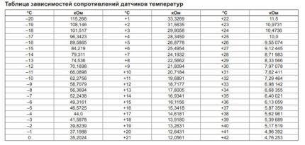
Failure of the t° air flow sensor – E4, the signal sounds 5 times. Broken wire or short circuit of heat exchanger t° sensor – E5, 6 times. Errors E4 and E5 are issued in case of voltage surges above or below standard values - 0.06-4.94 V.
Causes:
- mechanism failure;
- The part is not connected correctly.
Solutions:
- check that the sensor is connected correctly using a voltmeter;
- compare the obtained resistance data with the tabular ones;
- if the indicators do not correspond, replace the spare part;
- otherwise, change the board.
Communication problem between display boards and indoor unit - E7, blinks 9 times.
Causes:
- tearing of wire connections in the electronic system;
- incorrect connection;
- board failure.
Solutions:
- check the integrity of the wires and the correctness of their connection to the boards;
- check the functionality of the multimeter control boards one by one;
- if necessary, replace them.
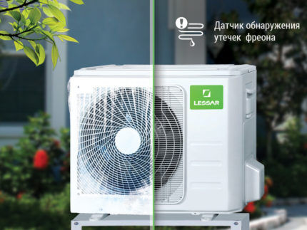
A coolant leak has been detected - EC, the light signal is displayed 7 times.
Causes:
- freon leaked;
- the temperature sensor is not functioning correctly;
- board malfunction;
- lack of sufficient air exchange in the outer part of the structure;
- contamination of the outdoor unit heat exchanger;
- track hall.
Solutions:
- restarting the system after a while;
- in cooling mode, you should check the actual temperature of the air masses entering the room;
- when warm air enters, it is necessary to check the presence of working fluid in the system and the pressure level;
- inspect the external part of the split system for contamination, remove it if necessary;
- if cool air comes out of the device, you will also need to diagnose the temperature sensor according to the scheme, as with code E4;
- If the part is working properly, you need to replace the control board.
Current overload error – F0, signals 1 time.
Causes:
- short circuit between turns;
- short circuit;
- making mistakes when filling with refrigerant, especially in winter;
- Compressor jamming.
Solutions:
- free access to the compressor;
- if the unit does not start when you turn on the equipment in cooling mode, you need to ring it and check the connecting circuits;
- eliminate short circuit in the wires;
- if a short circuit is detected, the compressor will need to be replaced;
- if there is no short circuit, check the serviceability of the sensor and power module and replace the entire board;
- if high pressure in the system persists, you need to clean the heat exchangers from dust and dirt.
After these steps, you need to turn on the air conditioner again and check if the error code occurs again. Repeated problem - detection of strong vibration, high pressure on the line indicate jamming of the compressor unit. If it is impossible to restore it, it should be replaced.
If the pressure remains the same high, the air conditioner will need to be recharged.
#2. Registration of external unit breakdowns
Problem with air temperature sensor – F1, the indicator flashes 2 times, the timer is constantly on.
Heat exchanger t° sensor error – F2, lights up 3 times, the timer is constantly on.
Short circuit/break of compressor discharge t° sensor – F3, flashes 4 times, the timer is highlighted.
Diagnosis of problems F1, F2, F3 is carried out in the same way as in the case of errors with t ° sensors of the indoor unit.
EEPROM error - F4, the indication lights up 5 times, but the timer does not turn off.In this case, the main processor does not receive a signal from the memory chip. Elimination of the breakdown is carried out, as in the internal part of the split system, by replacing the board.
Fan speed control failure – F5, the indication lights up 6 times, the timer is on. Triggers when the rpm drops below 300 per minute.
Causes:
- error connecting wired connections;
- The motor and fan impeller do not work;
- The defective board needs to be replaced.
Solutions:
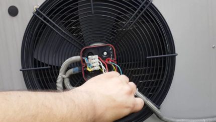
- Repair of a fan with a built-in microcircuit. When the climate control equipment is in standby mode and connected to the network, measure the voltage between contacts 1 and 3, 4 and 3 of the mechanism. If the obtained value does not fall within the range specified in the table, the board will need to be replaced.
- Diagnostics of fans of models WZDK36-38G-W, WZDK40-38G-W-1 with a control chip on the board. To check the functionality of the node, you need to connect it to the network. If the mechanism works, the board will need to be replaced. If the fan does not turn on, you need to check the resistance of the windings on each pair of pins.
The methods discussed will allow you to completely eliminate the error and restore the correct operation of the device.
| № | Wire color | Voltage, V | Signal |
| 1 | Red | 280-380 | Vs/Vm |
| 2 | — | — | — |
| 3 | Black | 0 | GND |
| 4 | White | 14-17,5 | Vcc |
| 5 | Yellow | 0-5,6 | Vsp |
| 6 | Blue | 14-17,5 | Fg |
Power module error and inverter module protection - P0, fault and timer indicator lights up 1 time. The code appears when the voltage that the power module sends to the compressor is exceeded or decreased.
Causes:
- incorrect connection;
- failure of the fan in the external device of the split system;
- failure compressor;
- main board malfunction;
- failure of the power module.
Solutions:
- first check that the compressor is connected correctly to the board;
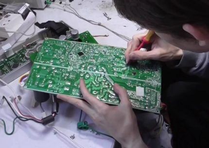
- inspect the power module, measure the resistance between P and terminals U, V, W, N, as well as N and U, V, W (should be equal to MΩ - infinity), replace it if necessary;
- a similar action must be carried out with the control board of the outdoor unit;
- check if the fan is broken and replace it if it fails;
- measure the compressor winding resistance and compare it with the table.
Protection against voltage surges in the system – P1, the error indicator and timer flash 2 times. Triggers at critically low and high values.
Causes:
- Electricity problems;
- interference in the air exchange system;
- freon leak;
- board operation error.
Solutions:
- check the presence of power in the system;
- If the parameters do not correspond, turn off the device;
- check the integrity of the wires and the correctness of their connection;
- measure the voltage between terminals P and N on the power module and, if the standard values do not correspond, replace it.
You will also need to additionally inspect the chokes and replace them if they break.
Protection against overheating of the compressor unit – P2, the error indicator and timer blink 3 times.
Causes:
- Electricity problems;
- blocking air exchange;
- coolant leak;
- board error.
Solutions:
- carry out diagnostics of the air exchange of the indoor and outdoor units, clean the heat exchangers if there is dust on them;
- disconnect the device from the power supply;
- after 10-15 minutes, measure the compressor t °;
- check that it is connected correctly, as well as overload protection;
- inspect the hydraulic circuit;
- check the resistance at the terminals of the protection unit, which normally should tend to 0;
- if large readings are received, it will need to be replaced;
- If the compressor is working properly, the cause of the Lessar air conditioner error code P2 is a faulty board that will need to be replaced in the outdoor unit.
Compressor starting problem - P4, the indicator and timer light up 5 times. The error is determined by checking communication signals, voltage, and the number of revolutions of the compressor shaft.
Causes:
- incorrect node connection;
- power module malfunction;
- compressor breakdown;
- The main control board has failed.
Solutions:
- check the correctness and quality of connection of the wires between the board and the compressor;
- inspect the IPM power module, and if it is faulty, replace it;
- If, after checking the resistance of the compressor winding, the indicators do not correspond to the norm, replace the unit.
If the error is displayed again, the control board will need to be replaced.
If error codes E, F are displayed, you must immediately disconnect the device from the power supply and eliminate the cause of the malfunction yourself or contact a service center.In the event of a P code fault, the unit will start immediately after the parameters are restored. If the air conditioner does not restart, you will need to check for errors and fix them.
Malfunctions in commercial air conditioners
In addition to errors in household appliances, in semi-industrial cassette systems most errors are identical, but other types of malfunctions also occur.
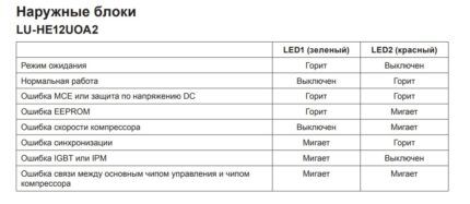
For example, models LS-HE12BCOA2/LU-HE12UOA2, LS-HE18BCOA2/LU-HE18UOA2 have the following additional codes:
- condensate container overflowing – E.E.;
- disruption of communication between the main and additional units of the system – E8;
- other errors (for several blocks) – E9;
- protection activation in case of low pressure – P6;
- power module error – P7;
- Evaporator protection for high temperature – J0;
- capacitor protection at high temperature – J1;
- PFC module protection – J3;
- failure of communication between compressor and control chips – J4;
- high pressure protection – J5;
- low pressure protection – J6;
- AC input voltage protection – J8.
When using the unit at low temperatures, the letter code LC may periodically appear on the screen.
In the Business series models LS/LU-H18/24BEA2, LS/LU-H36/41/48/60BEA4 the following errors occur in the internal design of the system:
| № | Code | Error name |
| 1 | E2 | Air temperature sensor malfunction |
| 2 | E3 | Pipe temperature sensor failure |
| 3 | E4 | Failure of the capacitor temperature sensor |
| 4 | E5 | Condenser drain pump t° sensor |
| 5 | E6 | External unit operation error |
| 6 | E7 | Microprocessor EEPROM failure |
| 7 | E8 | Condensate container overflowing |
Error codes of the external unit are displayed by LED1, LED2 and LED3 indicators.
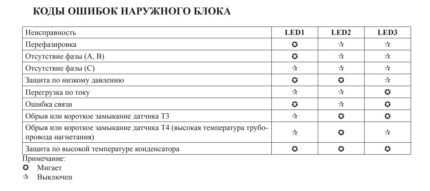
Troubleshooting problems in the operation of commercial air conditioners should be performed according to similar algorithms discussed in the section on solving errors in household units.
Conclusions and useful video on the topic
An example of the correct operation of a Lessar device:
Location of the main components and parts of the air conditioner for debugging them in case of errors, considered using the example of the Rational model range:
To eliminate any malfunction in a household or semi-industrial air conditioner Lessar, it is necessary to study in detail the design features of the system units. The hydraulic and electrical circuits specified in the technical instructions will allow you to carry out self-diagnosis of the device, as well as independently repair failed parts and microcircuits.
In the block below you can leave a comment, ask a question and post a photo on the topic of the article. Here you can talk about your own experience in identifying code violations and fixing the problem yourself. Please share useful information that may be useful to site readers.


Good afternoon. When the Air Conditioner is turned on, P6 appears on the display, we don’t know what to do. Help me please.
Air conditioner filled with ceiling Lessar mdou-60hn1-l when starting on heat, do not turn on the red def/fan indicator on the indoor unit. The air conditioner does not reach the set temperature mode, but it works. What could be the reason?