Gas filters: types, design, purpose and features of choosing a gas filter
A necessary technical device of the gas distribution system is a gas filter - a device that performs the functions of basic cleaning of the working environment from contaminants. But how does it work and is it possible to do without it? This is exactly what we will talk about in our publication - we will look at the design features of filters and their varieties.
We will also provide recommendations on the correct choice of the appropriate option, based on the characteristics of operation. In addition to the material presented, we will select visual photos, diagrams and thematic videos.
The content of the article:
Design and operating features of the filter
Thanks to elements such as filters installed on the line, long-term operation of control and measuring equipment, shut-off valves and other significant components is ensured. Therefore, equipping gas systems with filter elements is not just desirable, but a mandatory condition, taking into account the technological features use of domestic gas.
Despite the apparent external simplicity of execution, gas filters are quite diverse in technical and operational terms. Thus, in practice, devices are used that structural design conditionally should be divided into corner And linear.

In addition, differences in gas filter designs also appear in direction of movement gas flow through the device. Accordingly, there are two types of execution: direct-flow And turning.
Traditionally, the housing part of gas filters is made of metals - cast iron, steel, aluminum, and here the variety should also be considered hull structures.
Finally, gas filters are also divided according to such criteria as filtration material:
- reticulate;
- cassette.
The first option is characterized by metal gridwoven from thin wire.
In the second case, we are usually talking about special stuffed cassettes, where a thin nylon thread or horsehair is used. These materials are additionally impregnated with special (viscine) oil.

The filter material used in the construction of gas filters must have appropriate chemical and physical properties and provide physical resistance to the working environment. All these nuances are taken into account during development and design.
How does the gas filter work from the inside?
Regardless of the variety of gas filter designs, almost all have a similar internal technological system, with the exception of some individual parts.
The picture below shows diagrams of typical gas filters that are quite widely used in the operation of gas networks.
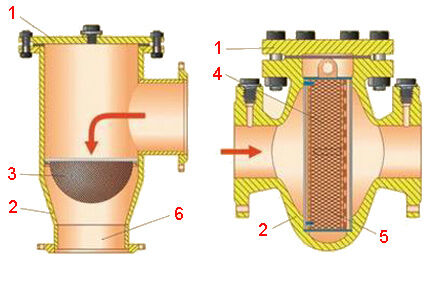
It is worth noting some subtleties of the internal design. For example, metal mesh filters tend to increase the degree of fineness of cleaning due to the accumulation of clogging. At the same time, the throughput of the filter element is correspondingly reduced. This effect is especially pronounced in multilayer structures.
In cassette systems, where horsehair is used as a filter element, on the contrary, the degree of purification weakens. This is due to the fact that the passing gas flow during operation of the device gradually carries away part of the filter material in the form of small particles.
Therefore, in order to reduce the number of entrained particles and maintain effective filtration, they strive to select the optimal speed of movement of the working medium when operating cassette-type filters.
Pressure drops and operating principles
In general, the maximum permissible pressure drop values when using gas filters should be 5,000 Pa (for mesh type elements) and 10,000 Pa (for cassette type elements).
Accordingly, at the time of starting operation of any type of gas filter, these parameters must correspond to the following numbers:
- 2,000 – 2,500 Pa (for mesh type elements);
- 4,000 – 5,000 Pa (for cassette type elements).
The operation of the filter mesh mechanism is not difficult to describe: household gas passing through the pipeline system meets the filter on the way and passes into the device through the inlet pipe.
Penetrating through a metal mesh, household gas is cleaned of foreign contents and then passes to the outlet pipe.

The debris retained by the mesh falls into the lower area of the mesh filter housing (in some designs) or is forcibly cleaned out. During maintenance, debris accumulated in the bottom area is removed through a hole, which remains closed with a plug during filter operation.
The cassette filter element works somewhat more “sophistically”, taking into account the characteristics of the material used. Inside the filter, along the flow of the working medium, there is a cassette filled with hair. Additionally, a bumper is installed in front of it - a metal plate that protects the cassette from damage to the rigid structure by large foreign bodies.
The design of such a cassette is simple - it is usually a rectangular (tubular) frame, the outer parts of which are covered with wire mesh. The internal area of the frame is filled with thread-like nylon or natural (horsehair) material. When filling, pack the homogeneous material tightly and add additional lubricant.
The gas passing through such a cassette is cleared of foreign contents and falls onto a perforated metal grid. This is another component of the cassette filter that prevents particles of filter material from being carried away into the system.
If the cassette becomes clogged, it is removed as part of maintenance and cleaned/rinsed with special solvents.
Optimal pressure drop control
Almost all gas filter designs provide operating pressure differential control. Some designs (usually outdated) for such purposes are equipped with fittings where an indicator can be connected.

Other, more modern products are equipped with an indicator element directly. Such an element is built into the body of the device and represents an information scale, usually divided by color zones (green and red). There are indicators with one and two pointers.
Option #1 - indicator with one pointer
Under normal operating conditions of the gas filter, the indicator pointer is in the green area, which clearly shows the optimal level of pressure drop.
If the indicator arrow moves to the area of the scale colored red, this factor indicates that the filter is clogged.
On such differential indicators, the primary attention of maintenance personnel is given to the red segment of the scale and the corresponding indicator. When a red arrow is present in the red segment area, the filter is subject to preventative maintenance followed by cleaning or replacing the filter material.
Option #2 - indicator with two arrows
For this version, the control scale is divided into two segments, colored black and red.Indicative elements (arrows) also correspond to the colors of the segments.
The black area is intended to control the pressure drop at the current time. The red color area is used to control the drop at moments of maximum consumption.

The peculiarity of such indicators is that while the indicator of the black segment of the scale has the ability to return towards the origin, the indicator of the red segment is not endowed with this ability.
If the red pointer detects an excessive difference, the arrow (red) stops irrevocably at the reached level. Returning to the zero mark is only possible manually during maintenance.
Features of choosing a gas filter
When selecting a suitable gas filter, the following features should be taken into account:
- pipeline diameterwhere installation is intended;
- gas consumption (calculated parameter);
- pressure — you need to know the value of the absolute pressure at the inlet of the filtering device;
- density — it is desirable to have data on the density of the gas medium.
Filter devices from different manufacturers differ in appearance and characteristics. However, each product is marked accordingly. Marking allows you to select a filter taking into account the main criteria.

In order to maintain a sufficient degree of purification by the filter element, the selection usually takes into account the limitation of the flow rate of the medium passing through the filter device.
The speed parameter is usually determined by the parameter of the maximum permissible pressure drop. If the filter is clean, then the drop is allowed at a level of no more than 50% of the maximum permissible value.
Usually, in order to accurately select a filter for a gas pipe, it is convenient to use special tables. If access to the tables is impossible or a unique selection is required, it is logical to use the calculation formula shown in the figure below.

Traditionally, the choice of gas filter is compared with diameter linear pipeline on which the device is supposed to be installed. In this case, the throughput of the device is connected with the flow parameters at the gas distribution point - they are guided by a similar value or higher.
Conclusions and useful video on the topic
Video about gas filters, their features and the need for their use:
Operation of gas lines without the use of filters will be ineffective and impractical.Under such operating conditions, there is a risk of rapid failure of process equipment, which affects the economic side of operating the systems. Of course, the lack of filters affects the safety of the equipment.
Would you like to supplement the above material with interesting facts? Or do you still have questions about the topic of the article? Ask them to our experts and other site visitors, write your comments and advice - the feedback block is located below.


