Grounding of electrical installations and equipment - types and rules
Grounding electrical installations is a prerequisite for the safe operation of any electrical equipment.Properly performed grounding can prevent serious injury and even save health or life, not to mention damage to expensive equipment.
The content of the article:
Classification of grounding systems
The old (sixth) edition of the PUE provided for 2 options for grounding electrical transformers and consumers. In this case, the classification of grounding schemes looked simple:
- Blind (solidly grounded) neutral bus. Connected directly to the ground loop on the distribution transformer. A pair of wires went to consumers. They had their own grounding.
- Remote or isolated neutral. The grounding bus was not connected to a circuit dug into the ground, but was carried out with a separate wire in addition to the two supply wires already laid.
In theory, the grounding system should have worked like a clock - it was simple and understandable to any electrician connecting an electrical installation to the network. For the most part, the grounding worked well as long as the voltage balancing and ground wire were done correctly.
Problems arose only when the load was uneven (usually in rural areas) or when the neutral was broken.At an isolated neutral there was always excess potential relative to ground zero, which was unsafe.
Even on the simplest lighting devices, refrigerators, not to mention more powerful electrical installations, a potential appeared, the magnitude of which was unsafe for human health and life.
Since 2009, the seventh edition of the PUE (Chapter 1.7) has defined new grounding schemes for electrical installations and introduced their classification and letter designation.
The modern classification presents 5 types of grounding of electrical installations:
- TN-C is an old version with a dedicated grounded “dead” neutral.
- Option TN-S with separated neutral and protective (ground) conductors.
- TN-C-S diagram. The neutral (N) is combined with the protective conductor PE.
- TT diagram. The protective conductor is connected to the individual grounding of the electrical installation.
- TI version with isolated neutral and own grounding of the electrical installation.
The first and last diagrams represent old systems for organizing the grounding of live parts that existed in the sixth and earlier editions of the PUE. They were included in the classification, since all electrical installations, transformers, electrical equipment, wiring in industrial and residential premises were carried out precisely according to these two schemes. Nobody changed anything. Neither the colors of the conductors, nor the connection diagram. Therefore, in the seventh edition of the PUE, 3 additional systems used in imported equipment were simply added to the classification.
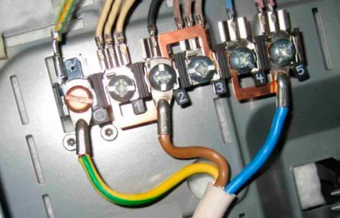
Now the grounded line relative to the electrical installation was designated “T”, and the isolated line – “I”. “N” indicated the neutral working wire. In the cable it is always blue and is used for electricity. Installed on insulated terminals.Regarding the “grounding” on the ground, there will be excess potential present on it.
To ground the housing of electrical installations and connect to the ground loop (on the ground), a wire marked PE (yellow-green, striped) is used. This is the true zero in the wiring.
Until 2009, the neutral (grounding) in the electrical installation was carried out with a black wire. Therefore, when inspecting or revising a switchboard, it makes sense to first look for the neutral yellow-green and black wires. Before starting work, check with an indicator which of them is responsible for grounding the electrical installation.
TN-C grounding system
This is an old scheme with a solidly grounded neutral for networks with electrical installations up to 1000 V, in some cases up to 6000 V. Here the working zero and grounding are combined in one bus. Despite the “outdated” solution, this option is still used in household appliances and in old power lines.
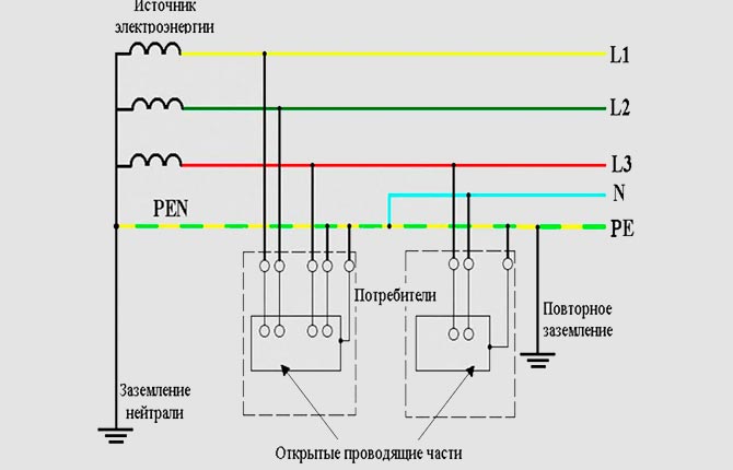
The TN-C system is considered one of the more effective ways to protect people from electric shock. But provided that the grounding device is installed correctly in the ground. In order for the grounding part of the wiring to work properly, it is necessary to update and periodically restore the circuit. This is the weakest point in the entire TN-C circuit.
Grounding system TN-S
The scheme appeared in Europe 60-70 years ago, and turned out to be very reliable, safe, but more expensive to maintain. It was not popular in the USSR.
The option with an isolated neutral is used only in electrical installations up to 1000 V. The TN-S circuit is used in conditions where it is not possible to establish effective grounding using a dissipative metal circuit in the ground.Sometimes used on mobile power generating units.
Imported household appliances, brought from the same Eastern Europe, surprised by the presence of an additional grounding terminal on the plug. TN-S is often called Euro-grounding, although this is not entirely true. A single-phase network with an operating voltage of 220 V is supplied to the apartment with 3 wires (phase, neutral and ground). For three-phase power supply of electrical installations, 5 conductors were required.
The TN-S system means that zero protective and “neutral” are separated along the entire line.
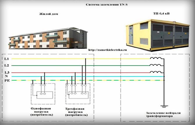
In this case, PN is the neutral (blue wire), PE is the pure zero “ground” (yellow-green striped conductor).
The TN-S system has a number of advantages:
- there is no need to bury the metal circuit in the ground;
- no interference from high frequency radiation;
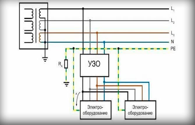
- It is possible to install an RCD device.
Devices or protective devices operate on the principle of measuring leakage current in a humid environment. As soon as the leakage current from the phase to the ground (wet floor, walls or any other surface) or to the neutral exceeds a safe threshold of 30 mA, the machine will disconnect the line from the power supply.
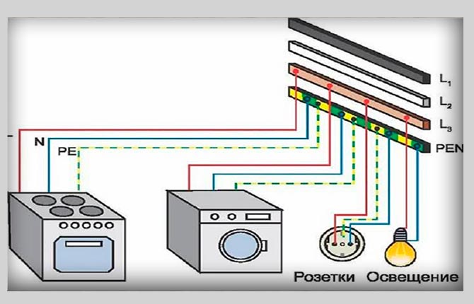
Grounding system TN-C-S
This option can be considered an intermediate solution or a way to eliminate the problem of the presence of old TN-C and more modern TN-S in the housing stock. The question is more than relevant due to the massive construction of new housing stock, as well as major renovations of old apartments.

TN-C-S combines elements of previous grounding systems. With the most advanced grounding system for electrical installations, TN-S, the cable to the apartment came to the distribution panel with a separated neutral and a protective line. Moreover, the entire bundle extended from the transformer substation.Now, a cable was supplied to a private house (to the entrance of a high-rise building) in which one common PE-N or PEN cable was used for protection and grounding (as well as neutral).
At the PEN input panel, 3 wires are reconnected:
- neutral, blue wire (N);
- protective, yellow-green PE wire;
- outlet to the ground bus of the local ground loop.
As a result, it turns out that it is possible to connect imported electrical installations, since there is a protective and neutral line. On the other hand, the wiring in the house or apartment is equipped with local grounding on the ground, which increases the level of safety.
The system seemed to combine the advantages of TN-C and TN-S, but at the same time inherited their disadvantages. For example, in the event of a break in the PEN line or if the tap to the additional ground loop has rotted (often happens), then an increased potential will come through the neutral to the body of the electrical installation. This is already fraught with electric shock.
TT grounding system
At first glance, a slightly unusual, but in fact very practical TT circuit with double grounding has long been widely used in the suburbs, rural areas, summer cottages and cottage villages.
In accordance with the seventh edition of the PUE (clause 1.7.3), the TT system is a circuit in which the neutral at the transformer substation (or distribution transformer) is solidly grounded, and a grounding circuit is also equipped for the open parts of the electrical installation. In this case, both groundings are electrically independent.
The system is simple and reliable, although before the advent of the PUE in the 2009 edition it was considered risky and was formally banned. Today, use for grounding electrical installations in private homes is permitted only if the following conditions are met:
- Arrangement of a complete grounding loop in the ground.
- Installation of a potential equalization system on all metal elements in the house.
- Use of RCD (residual current device).
Clause 1.7.59 of the PUE determines the circuit according to which RCD devices should be turned on.
The most difficult part will be making the ground loop. It’s not enough to dig a trench and weld a perimeter from an old metal corner. The contact surface between metal and soil must be large enough so that the grounding resistance, measured with a special device, does not exceed the calculated value in Ohms. It (R) should not exceed the quotient of 50 divided by the maximum value of the RCD operation current. From several devices, the one with the maximum current is selected.
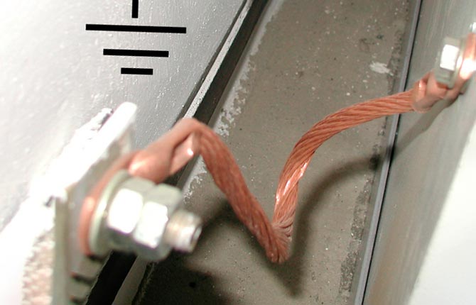
The potential grounding system is a (copper) conductor with which the main metal objects on which excess potential may appear are connected to ground. It could be:
- electrical installation housing;
- Appliances;
- steel frames;
- ventilation;
- water and sewer pipes.
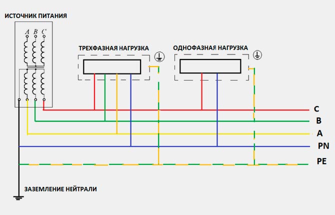
IT grounding system
An old version, widely used in the vast expanses of the former USSR during the mass construction of “Khrushchev” buildings. The IT grounding scheme is a classic one with an isolated neutral.
The housing of the consumer electrical installation receives only 3 wires (three-phase current) and 2 for a single-phase network. The zero on the consumer's network is grounded into the ground according to existing grounding rules.
Advantages of the scheme:
- Accidentally touching the contacts or one live wire with your hand, but without insulation, leads to a slight tingling sensation instead of a full-fledged electric shock.
- Small leakage current when the zero in the wiring is shorted to a grounded housing.
- A wire falling onto the ground (a break on a pole) does not result in the appearance of step voltage.
Among the disadvantages, one can note the impossibility of using an RCD. In addition, when a powerful low-resistance load is switched on between zero and one of the phases, an excess potential of significant magnitude appears on the third wire.
Requirements for grounding electrical installations up to 1000 Volts
The installation of grounding and protective devices on the transformer or generator side is of little interest to consumers. For those who operate electrical installations and use household appliances, it is more important to do the grounding correctly.
The requirements apply to grounding electrical installations up to 1000 W:
- Ensure a reliable connection with minimal current resistance between the electrical installation housing and the ground.
- Ensure normal dissipation of excess potential that enters the electrical installation body as a result of an emergency.
- Prevent step voltage from appearing.
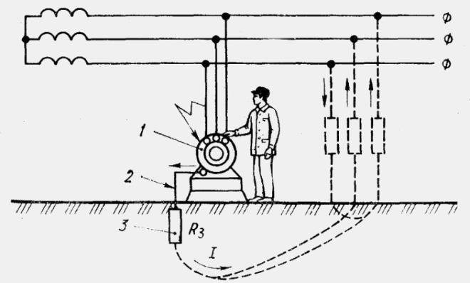
On a properly equipped grounding, in the event of an insulation breakdown, the current will flow along the path of least resistance - through the metal parts of the housing to the grounding bus into the ground. Since at the substation or in the intermediate section the zero is also grounded into the ground, the current will flow through the ground masses in the direction of the transformer. Due to the resistance of the soil masses, the electric current will dissipate, losing potential.
In this case, touching the grounded body of the electrical installation with a dry hand will be absolutely safe, even if it is partially affected by increased voltage. The resistance of normal grounding rarely exceeds several ohms. For dry human skin this figure is several thousand Ohms, for damp (but not wet) – from 500 Ohms to 1000 Ohms.
The basic requirements for the arrangement of protective grounding for voltages of 42-380 V for alternating current and 110-440 V for direct current under special conditions (the presence of highly conductive environments) are described in GOST 12.1.013-78. In other cases, grounding of electrical installations above 380 V AC and 440 V DC is carried out on the basis of GOST 12.1.030-81.
Natural grounding
These are objects and environments that facilitate the flow of voltage potential into the current-dissipating earth mass. Grounding electrodes can be artificial and natural. The first include specially manufactured scattering masses and devices with specified characteristics. The second includes any metal objects on the surface of the soil, placed in the near-surface layer of soil. It can be:
- steel water pipes;
- powerful cables with a metal (lead) protective sheath;
- reinforcement of walls and foundations;
- cast iron sewer lines;
- racks;
- elements of vertical holders.
All of this is in one way or another in contact with the soil and, in the presence of a conducting medium (humidity), can act as natural grounding. In addition to the ability to transfer potential to the ground, natural grounding electrodes are characterized by the ability to dissipate current, partially extinguish and convert its energy into heat.
Natural grounding conductors can help dissipate excess potential, but can also cause electric shock if the grounding is faulty. For example, if in the bathroom the socket or electrical installation housing is not grounded or the grounding bus is faulty. Plus, the floor is on a reinforced concrete floor slab.
Concrete easily absorbs water and moisture seeps to the steel reinforcement (one of the types of natural grounding).Excess potential from the phase in the socket can flow down the wet surface to the water mixer. If you stand on the floor with your bare feet and touch the tap, you can get a strong electric shock. Therefore, the floor in the bathroom or kitchen must be covered with waterproofing.
The importance of current flow resistance
The most important characteristic of grounding is the value of the resistance to dissipate excess potential. The operation of the grounding loop can be represented as a closed circuit in which the current from the phase line enters the body of the electrical installation and is then directed along the path of least resistance to the ground.
Electric current flowing into the ground loop must be effectively extinguished. Therefore, the grounding loop is made not just from massive steel profiles or pipes with a relatively large surface area. The perimeter should be large - this improves the “spread” of the current in the conducting mass.
Therefore, grounding of powerful electrical installations with an operating voltage of 380–660 V is done in the form of a rectangular circuit with a large perimeter. The larger the rectangle, the better the current dissipation and the lower the resistance.
It is also not recommended to greatly reduce the resistance of the grounding device. The amount of current dissipation must comply with the recommendations of the PUE and GOST, and most importantly, be relatively constant at any time of the year.
This is especially important in cases where a substation or transformer with a grounded neutral is located near the house. For example, if a private house is in an urban area with numerous underground communications, then it is quite possible that steel water pipes can sharply reduce the resistance of the “ground” and lead to an accident at the electrical installation.
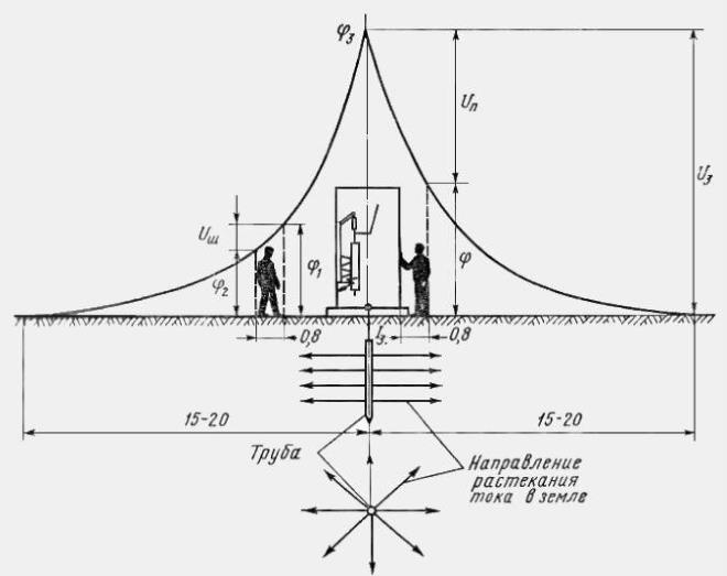
Sometimes owners limit themselves to conventional pin grounding. This is simpler and cheaper than a loop, and is quite sufficient for small household electrical installations. But in this case a second problem arises. The electric current entering the soil from the body of the electrical installation through the grounding bus itself creates additional potential on the ground. The higher the voltage on the line, the higher the potential at the drain. Especially if the parts of the grounding loop are dug to a shallow depth.
Since the contact area of the metal rod with the ground is small, the resistance of the ground loop is large. The excess potential spreads radially from the rod, decreasing on the surface as the installation point moves away. Step voltage appears.
This means that in rain, fog or sleet, anyone who chooses to walk in wet shoes near the ground pin will receive a painful electric shock to their feet.
If you find yourself in such a zone, you can only get out of it by jumping, pressing your feet tightly together.
Typically, such zones occur near high-voltage electrical installations.
Grounding operation in case of violation of the protective insulation of live parts
The situation when the insulating sheath of the cable on the line was broken is not considered. The network has its own grounding and if an insulation breakdown occurs, the machine will disconnect the line.
At home or in the workplace, phase insulation damage is possible:
- In the TN-S system (universally installed in modern residential premises), excess potential will fall on the housing, and accordingly, the current will flow through the protective conductor PE into the ground loop connected to the switchboard.
- If the phase insulation is not broken, but the wiring burns in small pulses.In damp rooms, you may feel a slight tingling sensation (potential shock) when touching metal parts or live parts. There will be no problem if there is an RCD on the line with damaged wiring - it will simply disconnect the wiring on the switchboard.
Approximately the same picture will be in the case of grounding household electrical installations according to the TN-C-S scheme. Only the excess potential will go into the grounding loop of the entrance. The only negative is that the common grounding device connected to the panel board of an apartment building may be broken or damaged. In this case, you can get an electric shock, since the PE protective conductor, which must be grounded, is also connected to the neutral leading to the substation.
TT and IT systems are not used in domestic conditions.
In the T-C circuit, if the insulation is damaged, the current will partially flow to the zero line and partially to the grounding loop buried in the courtyard of the house. If it is working properly, then nothing will happen. Simply, in the event of a short circuit, the automatic packetizer will de-energize the line. It is safe to touch the body without touching other metal objects.
Sometimes a slight, barely noticeable blow still occurs. But this phenomenon is due to the fact that the human body has its own capacity.
Protection of electrical equipment in workshops
In production premises, as a rule, a significant amount of main and auxiliary equipment is installed. In addition, the workshop must have ventilation and lighting systems that are connected to a separate line.
Lighting must be independent in accordance with fire safety rules. Ventilation is additionally equipped with a whole grid of auxiliary (insulated) conductors with arresters and artificial grounding conductors.With their help, the high-voltage potential of static electricity that accumulates on ventilation ducts during air movement is removed.
Both grounding systems must be galvanically independent from the main electrical equipment protection system. TN-C and TN-S can be used in small isolated rooms with a maximum voltage of electrical installations up to 380 V.
To protect electrical installations in workshops, 2 grounding systems are used - TT and TI. In addition, all communications and metal parts with which maintenance workers come into contact are grounded. The secondary grounding system provides for connecting reinforced concrete slabs of floors, walls, staircases with railings to additional grounding.
Grounding of welding machines
This type of electric machine is excluded from a number of electrical installations for many reasons. First of all, because of the huge currents, due to which secondary interference is formed on the cables of the welding machine. If in ordinary electrical appliances a potential difference of several volts was induced on the housing from a running engine or power supply, then with a welder the induced voltage can be several tens of volts.
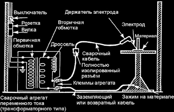
The second important point is the inductive and periodic nature of the load. In addition, significant currents reach the zero of the welding machine, and the potential surge at the moment of switching on can briefly reach more than a hundred volts.
Features of grounding welding machines:
- Each electrical installation must have its own individual grounding circuit.
- Connecting several devices to one ground is not allowed.
- A terminal for a screw - a wing nut or a clamp - must be welded on the electric welding body; the contact from the busbar to the ground must be clamped mechanically.
According to PUE-7 (clauses 1.7.112-1.7.226), the grounding wire for a stationary electrical installation must have a cross-section of at least 10 mm2 for copper, 16 mm2 for aluminum, 75 mm2 for steel.
Welding inverters and all similar types of electrical installations can be grounded using an isolated neutral circuit, provided that an RCD is installed on a dedicated line.
Protection of mobile installations
As a rule, we are talking about electrical installations located on vehicle bases. For repair shops, mobile welding machines, installed on unequipped sites for a relatively long time (up to 2 weeks), grounding according to the TT circuit can be used.
For mobile measuring laboratories, radio stations, equipment with a small current load, the TN-S circuit is used. In both cases, grounding is equipped using a standard aluminum grounding stake with a screw attachment. It must be buried in the ground to a depth of at least 80 cm, if there is grass on the site. This indicates that the soil is moist. For dry areas for grounding electrical installations, use a circuit of 3 steel pins driven to a depth of 100-120 cm.
Portable ground electrodes can be used. They are used by electricians to repair and maintain outdoor electrical installations of all types. Any station generator, the transformer has its own capacitance, and the presence of overhead lines (wires) suspended on poles above the ground only increases the value of C.Therefore, after de-energizing, the second action is to install “ground” (portable grounding) on all lines. They can also be used for temporary grounding of mobile electrical installations.
Protection of electrical appliances
Protective grounding schemes for industrial electrical installations and devices are described in detail in the technical documentation. But household appliances, even relatively complex ones, such as a boiler or washing machine, are not equipped with a grounding device circuit. It is believed that representatives of the company will install the electrical installation - they will do the grounding.
Any household electrical appliance with an operating voltage of 42 V AC or DC voltage of 110 V or higher must be grounded. This is the requirement of clause 1.7.33 of the PUE. Electricians usually make an exception for lighting systems with which there is no constant contact. Everything else that we handle with our hands and has a connection to the 220 V network is definitely grounded.
Typically, the TN-C-S or TN-C circuit is used for household electrical installations. The protective PE present in the socket is used. It also goes to the distribution board and general grounding.
If the apartment has powerful electrical installations (boiler, washing machine, heating boiler), then it is better to make individual grounding with a circuit in the ground. Moreover, it is not a fact that the common “ground” on the entrance panel of a high-rise building, on which 20-25 apartments hang, will work 100% in the event of force majeure.
Electrical installations equipped with switching power supplies also need to be grounded. This will remove high-frequency interference and eliminate the risk of phase contact with the housing through the leakage current of the network filter.
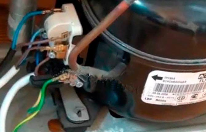
Be sure to ground the refrigerator; this is the second statistically (after electric boilers) cause of electric shocks.
Motor Grounding Basics
Approximately half of all electrical installations are equipped with electric motors, most often AC motors. A feature of the compressor motor is a large number of wires laid in the stator or rotor winding. Moreover, the wires are in very thin, easily damaged varnish or enamel insulation.
Therefore, a malfunction of the electric motor most often causes electric shocks:
- The insulation is minimal, the windings become very hot.
- The wire may be in contact with the housing.
- The rotor rotates even after the electrical installation is turned off and can release stored energy both into the line and to the housing.
To ground electric motors, a dissipative circuit is used, connected by a wire or bus through a terminal on the housing. The supply wiring is connected to the engine via the TT system. If several electric motors are installed in the room, then they are all connected to the current-carrying busbar with an independent wire parallel to the busbar - no series connections are allowed.
For low-power 220 V electric motors, an exception is sometimes made with a protective wire, but only when the motor is installed on a metal base and fixed with crutch pins driven into the ground to a depth of at least 60 cm.
But even in this version of the “ground”, servicing the electric motor must begin with a complete de-energization and connecting an additional remote grounding to the housing. First, a grounding loop is installed, and only then is it attached to the motor housing. This is a universal rule for connecting all types of grounding.
Results
Grounding an electrical installation is the only way to protect against electric shocks, both from the supply transformer and from the residual potential remaining on the line. Despite the fact that some practical aspects are not detailed in the PUE, when working with electrical equipment you need to use the rules, and only then the manufacturer’s instructions.
Tell us about your experience in grounding installations - what problems you encountered and how they were solved. Save the article in your bookmarks so that useful information is not lost.


Do the grounding the old fashioned way with a 15-20 square meter wire and a 10-15 kg piece of iron buried in clay soil. It can be in the basement, it can be under the window of the house. This is the only safe option; it’s not for nothing that they invented it back in the USSR and forced to use it. Neither a broken neutral after a storm nor fools who climb into the switchboard are scary.
I grounded the boiler at the dacha, I thought it was safer. I scored four corners, everything was as it should be. And he gets an electric shock. It turned out that a neighbor in his summer cottage, his house nearby, also made grounding next to mine. And he waters all the raspberries between the houses, and now he’s electrocuting me. What to do?