Solar battery charge controller: circuit, operating principle, connection methods
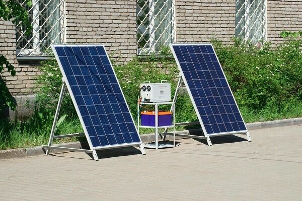
Solar energy is so far limited (at the household level) to the creation of photovoltaic panels of relatively low power.But regardless of the design of the photoelectric converter of solar light into current, this device is equipped with a module called a solar battery charge controller.
Indeed, the solar photosynthesis installation includes a rechargeable battery - a storage device for the energy received from the solar panel. It is this secondary energy source that is primarily served by the controller.
In the article we present, we will understand the design and operating principles of this device, and also consider how to connect it.
The content of the article:
Solar Controllers
An electronic module called a solar controller is designed to perform a number of control functions during the charging/discharging process solar battery battery.
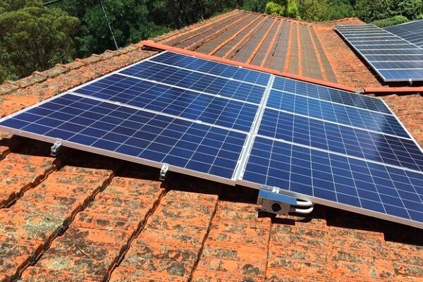
When sunlight falls on the surface of a solar panel installed, for example, on the roof of a house, the device's photocells convert this light into electric current.
The resulting energy, in fact, could be supplied directly to the storage battery. However, the process of charging/discharging a battery has its own subtleties (certain levels of currents and voltages). If you neglect these subtleties, the battery will simply fail in a short period of operation.
To avoid such sad consequences, a module called a charge controller for a solar battery is designed.
In addition to monitoring the battery charge level, the module also monitors energy consumption.Depending on the degree of discharge, the solar battery charge controller circuit regulates and sets the current level required for the initial and subsequent charge.

In general, in simple terms, the module provides a carefree “life” for the battery, which periodically accumulates and releases energy to consumer devices.
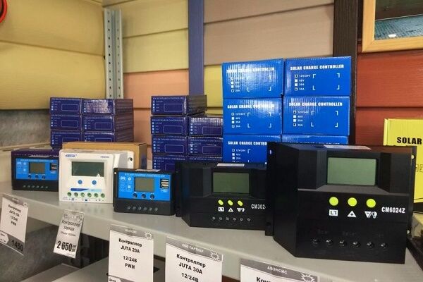
Types used in practice
At the industrial level, two types of electronic devices have been launched and are being produced, the design of which is suitable for installation in a solar energy system:
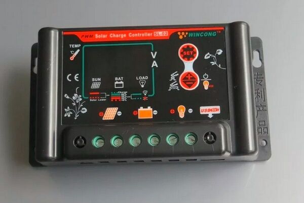
- PWM series devices.
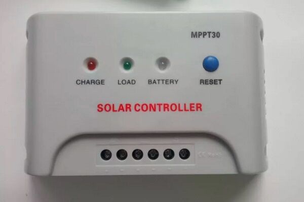
- MPPT series devices.
The first type of controller for a solar battery can be called “old man”. Such schemes were developed and put into operation at the dawn of the development of solar and wind energy.
The operating principle of the PWM controller circuit is based on pulse width modulation algorithms. The functionality of such devices is somewhat inferior to the more advanced devices of the MPPT series, but in general they also work quite effectively.

Designs using Maximum Power Point Tracking technology (tracking the maximum power limit) are distinguished by a modern approach to circuit solutions and provide greater functionality.
But if we compare both types of controller and, especially, with a bias towards the domestic sphere, MPPT devices do not look in the rosy light in which they are traditionally advertised.
MPPT type controller:
- has a higher cost;
- has a complex configuration algorithm;
- gives a gain in power only on panels of a large area.
This type of equipment is more suitable for global solar energy systems.

For the needs of an ordinary user from a domestic environment, who, as a rule, has small-area panels, it is more profitable to buy and operate a PWM controller (PWM) with the same effect.
Block diagrams of controllers
Schematic diagrams of PWM and MPPT controllers to consider them with a layman's eye are too complex a point associated with a subtle understanding of electronics. Therefore, it is logical to consider only structural diagrams. This approach is understandable to a wide range of people.
Option #1 - PWM devices
The voltage from the solar panel travels through two conductors (positive and negative) to the stabilizing element and the separating resistive circuit. Due to this piece of the circuit, potential equalization of the input voltage is obtained and, to some extent, they organize protection of the controller input from exceeding the input voltage limit.
It should be emphasized here: each individual device model has a specific input voltage limit (indicated in the documentation).

Next, the voltage and current are limited to the required value by power transistors. These circuit components are in turn controlled by the controller chip through the driver chip. As a result, the output of a pair of power transistors sets the normal value of voltage and current for the battery.
The circuit also contains a temperature sensor and a driver that controls the power transistor, which regulates the load power (protection against deep discharge of the battery). The temperature sensor monitors the heating status of important elements of the PWM controller.
Usually the temperature level inside the case or on the heatsinks of power transistors. If the temperature goes beyond the limits set in the settings, the device turns off all active power lines.
Option #2 - MPPT devices
The complexity of the circuit in this case is due to its addition to a number of elements that build the necessary control algorithm more carefully, based on operating conditions.
Voltage and current levels are monitored and compared by comparator circuits, and based on the comparison results, the maximum output power is determined.

The main difference between this type of controller and PWM devices is that they are able to adjust the solar energy module to maximum power, regardless of weather conditions.
The circuitry of such devices implements several control methods:
- disturbances and observations;
- increasing conductivity;
- current sweep;
- constant voltage.
And in the final segment of the overall action, an algorithm for comparing all these methods is also used.
Controller connection methods
Considering the topic of connections, it should immediately be noted: for the installation of each individual device, a characteristic feature is working with a specific series of solar panels.
So, for example, if a controller is used that is designed for a maximum input voltage of 100 volts, a series of solar panels should output a voltage no greater than this value.

Before connecting the device, you need to decide on the location of its physical installation. According to the rules, the installation location should be chosen in dry, well-ventilated areas. Avoid the presence of flammable materials near the device.
The presence of sources of vibration, heat and humidity in the immediate vicinity of the device is unacceptable. The installation site must be protected from precipitation and direct sunlight.
Connection technology for PWM models
Almost all manufacturers of PWM controllers require that the devices be connected in the exact sequence.
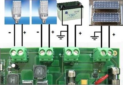
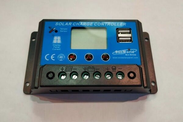
Peripheral devices must be connected in full accordance with the designations of the contact terminals:
- Connect the battery wires to the battery terminals of the device in accordance with the indicated polarity.
- Switch on the protective fuse directly at the point of contact of the positive wire.
- Attach the conductors coming from the solar panel battery to the controller contacts intended for the solar panel. Observe polarity.
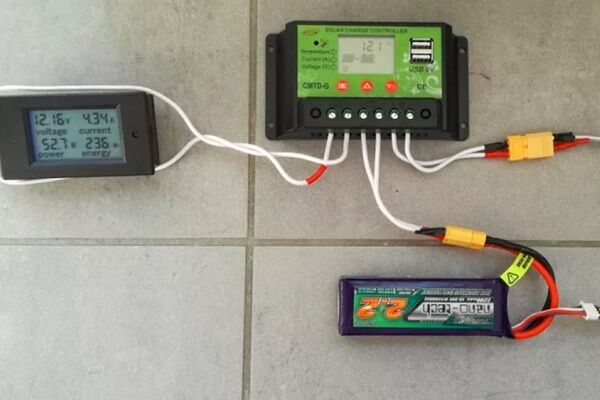
- Connect a test lamp of the appropriate voltage (usually 12/24V) to the load terminals of the device.
The specified sequence must not be violated. For example, connecting solar panels first when the battery is not connected is strictly prohibited. By doing this, the user runs the risk of “burning” the device. IN this material The diagram for assembling solar panels with a battery is described in more detail.
Also, for PWM series controllers, it is not permissible to connect a voltage inverter to the controller load terminals. The inverter should be connected directly to the battery terminals.
Procedure for connecting MPPT devices
The general physical installation requirements for this type of device do not differ from previous systems. But the technological setup is often somewhat different, since MPPT controllers are often considered more powerful devices.

For example, for powerful systems, these requirements are supplemented by the fact that manufacturers recommend using a cable for power connection lines designed for a current density of at least 4 A/mm2. That is, for example, for a controller with a current of 60 A, you need a cable to connect to the battery with a cross-section of at least 20 mm2.
Connecting cables must be equipped with copper lugs, tightly crimped with a special tool. The negative terminals of the solar panel and battery must be equipped with adapters with fuses and switches.
This approach eliminates energy losses and ensures safe operation of the installation.

Before connecting solar panels When connecting to the device, make sure that the voltage at the terminals corresponds to or is less than the voltage that can be supplied to the controller input.
Connecting peripherals to the MTTP device:
- Switch the panel and battery switches to the “off” position.
- Remove the protective fuses on the panel and battery.
- Connect the battery terminals with a cable to the controller terminals for the battery.
- Connect the terminals of the solar panel with a cable to the controller terminals indicated by the corresponding sign.
- Connect the ground terminal to the ground bus with a cable.
- Install the temperature sensor on the controller according to the instructions.
After these steps, you need to reinsert the previously removed battery fuse and turn the switch to the “on” position. A battery detection signal will appear on the controller screen.
Next, after a short pause (1-2 minutes), replace the previously removed solar panel fuse and turn the panel switch to the “on” position.
The device screen will show the voltage value of the solar panel. This moment indicates the successful launch of the solar energy installation.
Conclusions and useful video on the topic
The industry produces devices that are multifaceted in terms of circuit designs. Therefore, it is impossible to give unambiguous recommendations regarding the connection of all installations without exception.
However, the main principle for any type of device remains the same: without connecting the battery to the controller buses, connection to photovoltaic panels is unacceptable. Similar requirements apply for inclusion in the scheme voltage inverter. It should be considered as a separate module connected to the battery via direct contact.
If you have the necessary experience or knowledge, please share it with our readers. Leave your comments in the block below. Here you can ask a question about the topic of the article.


Initially, when installing solar panels to supply electricity to our small country house, a PWM type controller was used. However, after five years of operation it failed. Subsequently, on the recommendation of the master, I purchased an MPPT type controller, which was successfully integrated into the circuit. After six months of flawless operation, it sparkled and its screen went dark. I called the technician again and replaced the block.
Now I’m worried, was it worth changing the proven PWM controller to the newfangled MPPT? What is the reason for such a fragility of the MPPT block?
Firstly, the PWM controller has a simpler structure; accordingly, this device has fewer elements that can fail. But the MPPT controller makes it possible to increase the charging current supplied to the batteries from solar panels by up to 30% when compared with conventional PWM controllers! So it makes sense to use more modern MPPT controllers.
Secondly, have you found out the reasons for the breakdown? I think that there is one of two things here: either a manufacturing defect, or an error in the installation process, which subsequently led to a breakdown.
Please write the reason why the new MPPT controller failed. Have you used warranty service? It’s just that in my memory, even the most budget models did not fail earlier than after three years of operation.
Hello! I wanted to install solar panels. Electrical consumption house energy 4 kWh/day. I calculated the battery capacity, I got about 450 A. To charge such a volume, 45 A are required. To give that much current, the power of the panel must be 1750 W (in this U = 38.9 V).
It turns out that not all controllers can accept current with such power. I’m actually not an expert on this topic, I don’t have anyone to consult with. Any advice?
The PWM controller has been working on the camper for 5 years. Panel power 140 W. The system works without any problems. Last winter I removed the battery for maintenance and forgot to turn off the SB first. I remembered this already at home on the 2nd or 3rd day, when I once again thought about why my alarm was whining slightly (after all, without a battery)? Well, I decided to find out when installing the battery on the car whether the controller had failed. I installed the battery after 2 months. For two months the controller “hung” on the solar panel and nothing happened to it. It's been working fine for a year now. And at first I was very worried whether something would happen to the controller if it and the panel were not turned off while driving (with the generator running). At one time I didn’t really find anything on the Internet, I tried it in practice, everything was OK. And this is a photo of a frozen and snow-covered panel 3 years ago, after trying to clean it with a broom (part of it is visible on the left, the hatch on the right). This shell lay for about a month, the battery then ran out and froze, but survived. Good luck to all!
There is a typo in the first version of the comment, read the bottom one.
Good afternoon. Tell me why to connect the load to the PWM controller and whether it is possible to do without it! And if not, which one is better to choose?