Chiller-fan coil system: principle of operation and arrangement of the thermoregulation system
The multi-zone chiller-fan coil climate system is designed to create comfortable conditions inside a large building.It works constantly - it supplies cold in the summer, and heat in the winter, warming the air to the set temperature. It’s worth getting to know her device, don’t you agree?
The article we propose describes in detail the design and components of the climate system. Methods for connecting equipment are given and discussed in detail. We will tell you how this thermoregulation system works and functions.
The content of the article:
Components of the chiller-fan coil circuit
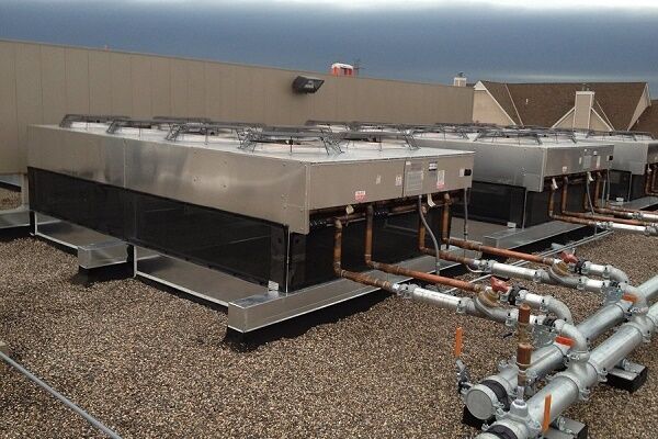
The role of the cooling device is assigned to the chiller - an external unit that produces and supplies cold through pipelines with water or ethylene glycol circulating through them. This is what distinguishes it from other split systems, where freon is pumped in as a coolant.
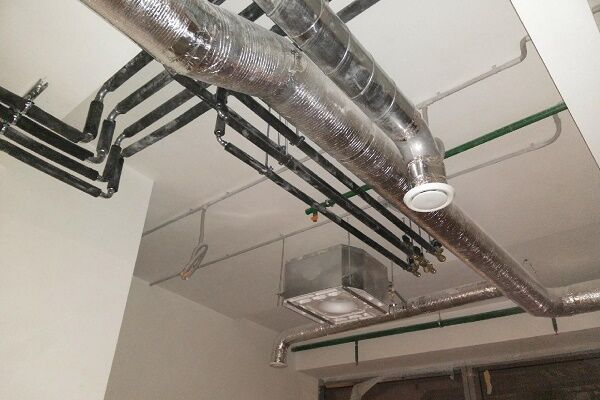
For the movement and transmission of freon, a refrigerant, expensive copper pipes are needed. Here, water pipes with thermal insulation cope well with this task. Its operation is not affected by the outside air temperature, while split systems with freon lose their functionality already at -10⁰. The internal heat exchange unit is a fan coil.
It receives liquid at a low temperature, then transfers the cold into the room air, and the heated liquid is returned back to the chiller. Fan coil units are installed in all rooms. Each of them works according to an individual program.

Typically, such systems are used in hypermarkets, shopping malls, structures built underground, and hotels. Sometimes they are used as heating. Then heated water is supplied to the fan coils through the second circuit or the system is switched to the heating boiler.
System design
According to the design, chiller-fan coil systems can be 2-pipe or 4-pipe. Depending on the type of installation, devices are distinguished between wall-mounted, floor-mounted, and built-in.
The system is evaluated according to the following basic parameters:
- chiller power or cooling capacity;
- fan coil performance;
- efficiency of air mass movement;
- length of highways.
The last parameter depends on the strength of the pumping unit and the quality of pipe insulation.
Connecting the chiller and fan coil
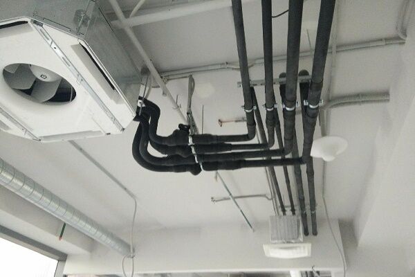
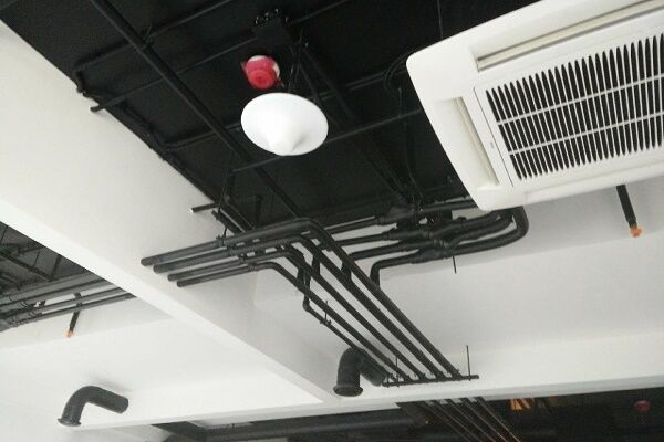
The smooth functioning of the system occurs through connection chiller with one or more fan coil units via thermally insulated pipelines. In the absence of the latter, the efficiency of the system drops significantly.
Each fine coil has an individual piping unit, through which its performance is adjusted both in the case of heat and cold generation. The refrigerant flow in a separate unit is regulated by means of special valves - shut-off and control valves.

If mixing of coolant and refrigerant is not allowed. the water is heated in a separate heat exchanger and the circuit is supplemented with a circulation pump. To ensure smooth adjustment of the flow of working fluid through the heat exchanger, a 3-way valve is used when installing the piping circuit.
If a two-pipe system is installed in a building, then both cooling and heating occurs due to a cooler - a chiller. To improve heating efficiency using fan coil units during the cold period, in addition to the chiller, a boiler is included in the system.
Unlike a two-pipe system with one heat exchanger, the four-pipe system contains 2 of these units. In this case, the fan coil can operate for both heating and cold, using in the first case the liquid circulating in the heating system.
One of the heat exchangers is connected to a pipeline with refrigerant, and the second to a pipe with coolant. Each heat exchanger has an individual valve controlled by a special remote control. If such a scheme is used, the refrigerant is never mixed with the coolant.
Since the temperature of the coolant in the system during the heating season ranges from 70 to 95⁰ and for most fan coil units it exceeds the permissible level, it is first reduced. That's why hot water‚ coming from the central heating network to the fan coil units ‚ passes through a special heating point.
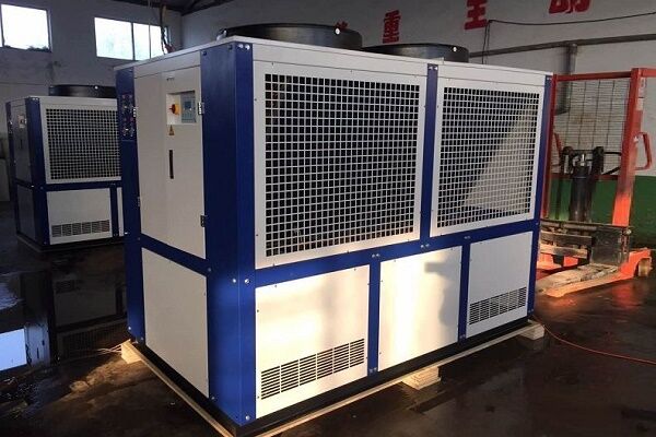
Main classes of chillers
The conditional division of chillers into classes occurs depending on the type of refrigeration cycle. Based on this feature, all chillers can be conditionally classified into two classes - absorption and steam compressor.
The structure of the absorption unit
An absorption chiller or ABCM uses a binary solution with water and lithium bromide present in it - an absorber. The principle of operation is the absorption of heat by the refrigerant in the phase of converting steam into a liquid state.
Such units use the heat generated during the operation of industrial equipment.In this case, an absorbent absorber with a boiling point significantly higher than the corresponding parameter of the refrigerant dissolves the latter well.
The operating diagram of a chiller of this class is as follows:
- Heat from an external source is supplied to a generator, where it heats a mixture of lithium bromide and water. When the working mixture boils, the refrigerant (water) completely evaporates.
- The steam is transferred to the condenser and becomes a liquid.
- The refrigerant enters the throttle in liquid form. Here it cools and the pressure drops.
- The liquid enters the evaporator, where water evaporates and its vapors are absorbed by a lithium bromide solution - an absorber. The air in the room is cooled.
- The diluted absorbent is reheated in the generator and the cycle starts again.
Such an air conditioning system has not yet become widespread, but it is fully in tune with modern trends regarding energy saving, and therefore has good prospects.
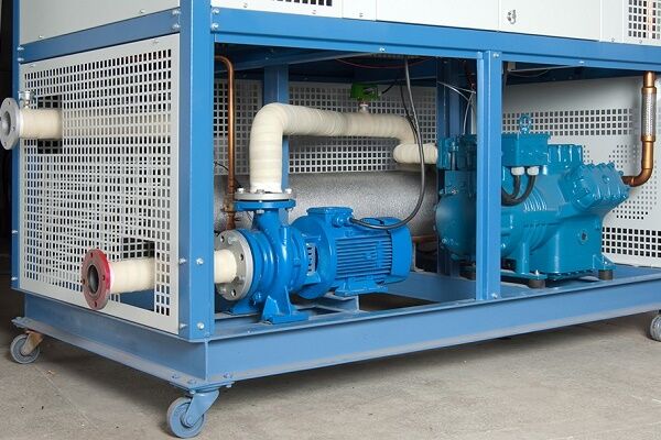
Design of vapor compression units
Most refrigeration units operate on the basis of compression cooling. Cooling occurs due to continuous circulation, boiling at low temperatures, pressure and condensation of the coolant in a closed-type system.
The design of a chiller of this class includes:
- compressor;
- evaporator;
- capacitor;
- pipelines;
- flow regulator.
The refrigerant circulates in a closed system. This process is controlled by a compressor, in which a gaseous substance with a low temperature (-5⁰) and a pressure of 7 atm is compressed when the temperature is raised to 80⁰.
Dry saturated steam in a compressed state goes into the condenser, where it is cooled to 45⁰ at a constant pressure and converted into liquid.
The next point on the movement path is the throttle (reducing valve). At this stage, the pressure decreases from the value corresponding to condensation to the limit at which evaporation occurs. At the same time, the temperature drops to approximately 0⁰. The liquid partially evaporates and wet steam is formed.

Having entered the heat exchanger - the evaporator, the working substance, a mixture of steam and liquid, gives off cold to the coolant and takes heat from the refrigerant, drying at the same time. The process occurs at constant pressure and temperature. Pumps supply low temperature liquid to the fan coil units. Having passed this path, the refrigerant returns to the compressor to repeat the entire vapor compression cycle again.
Specifics of a vapor compression chiller
In cold weather, the chiller can operate in natural cooling mode - this is called free cooling. At the same time, the coolant cools the street air. Theoretically, free cooling can be used at an external temperature of less than 7⁰C. In practice, the optimal temperature for this is 0⁰.
When configured in “heat pump” mode, the chiller operates for heating.The cycle undergoes changes, in particular, the condenser and evaporator exchange their functions. In this case, the coolant must be heated rather than cooled.

This mode is most often used in large offices, public buildings, warehouses. The chiller is a refrigeration unit that produces 3 times more cold than it consumes. Its efficiency as a heater is even higher - it consumes 4 times less electricity than it produces heat.
What is the difference between refrigerant and coolant?
A refrigerant is a working substance that, during the refrigeration cycle, can exist in different states of aggregation at different pressure values. The coolant does not change phase states. Its function is to transfer cold or heat over a certain distance.
The transport of refrigerant is controlled by a compressor, and the coolant is transported by a pump. The temperature of the refrigerant can fall below the boiling point or rise beyond it. The coolant, unlike the refrigerant, constantly operates at temperatures that do not rise above the boiling point at the current pressure.
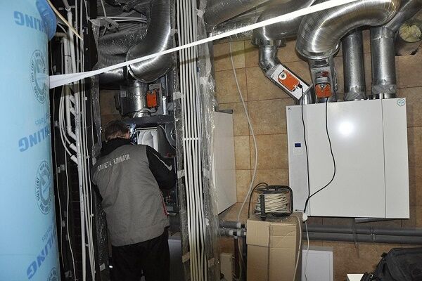
The role of the fan coil in the air conditioning system
Fan coil is an important element of a centralized air conditioning system. The second name is fan coil. If the term fan-coil is translated from English literally, it sounds like a fan-heat exchanger, which most accurately conveys the principle of its operation.

The purpose of the device is to receive media at low temperatures. The list of its functions also includes both recirculation and cooling of air in the room where it is installed, without the intake of air from outside. The main elements of the fan-coil are located in its body.
These include:
- centrifugal or diametrical fan;
- heat exchanger in the form of a coil, consisting of a copper tube and aluminum fins mounted on it;
- dust filter;
- Control block.
In addition to the main components and parts, the design of the fan coil unit includes a tray for collecting condensate, a pump for pumping out the latter, an electric motor, through which the air dampers are rotated.

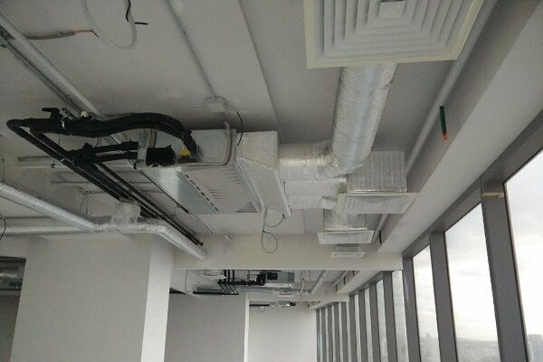
Depending on the installation method, there are ceiling fan coils, duct units, mounted in ducts through which air flows, unframed units, where all elements are mounted on a frame, wall-mounted or console units.
Ceiling devices are the most popular and have 2 versions: cassette and duct. The first ones are installed in large rooms with suspended ceilings. The housing is located behind the suspended structure. The bottom panel remains visible. They can disperse air flow on two or all four sides.

The need for cooling does not always exist, therefore, as can be seen in the diagram depicting the operating principle of the chiller-fincoil system, a container is built into the hydraulic module that acts as an accumulator for the refrigerant. The thermal expansion of water is compensated by an expansion tank connected to the supply pipeline.
They control fan coils in both manual and automatic modes. If the fan coil operates for heating, then the cold water supply is manually cut off. When it is working for cooling, the hot water is shut off and the path is opened for the flow of cooling working fluid.

To operate in automatic mode, the panel sets the temperature required for a specific room. The set parameter is maintained by means of thermostats that adjust the circulation of coolants - cold and hot.

Since any large building has zones with different temperature requirements, each of them must be served by a separate fan coil unit or a group of them with identical settings.
The number of units is determined at the system design stage by calculation. The cost of individual components of the chiller-fan coil system is quite high, therefore both the calculation and design of the system must be performed as accurately as possible.
Conclusions and useful video on the topic
Video #1. Everything about the design, operation and principle of operation of the thermoregulation system:
Video #2. On how to install and commission the chiller:
Installation of a chiller-fan coil system is advisable in medium and large buildings with an area exceeding 300 m². For a private home, even a huge one, installing such a thermoregulation system is an expensive pleasure. On the other hand, such financial investments will provide comfort and well-being, and this is a lot.
Please write comments in the block below. Ask questions about points of interest, share your own opinions and impressions. Perhaps you have experience in the installation of a chiller-fan coil climate system or a photo related to the topic of the article?


