How to install a circuit breaker: step-by-step installation instructions
Electrical panels located on the landings of apartment buildings are under the control of electricians from the management company.However, you must agree that every home craftsman is obliged to know the purpose of electrical devices enclosed in a metal box.
We suggest you figure out how to install a circuit breaker if an urgent need arises. We will tell you how the machine works and provide recommendations for choosing an electromechanical device.
This knowledge will help you replace the device yourself and take action in an emergency when the machine has tripped.
The content of the article:
Why is electrical knowledge necessary?
Information about electrical devices known from school physics lessons is not enough for practical use.
The average consumer more often encounters circuit breakers, since they are the ones that trip due to network overloads. It is not enough to simply return the lever to its usual position; you must definitely understand the reasons for the shutdown, otherwise the situation may repeat itself in the near future.

Do you need to be able to change the automation yourself? We recommend that you first study the theory, and at the first shutdown, practice.
The fact is that it is not always possible to get quick help from professionals: on days off, electricians rest like everyone else. And if the house is located in a country house or in a village, it is better to become thoroughly familiar with the electrical network and related devices.
Design and purpose of the machine
Despite the name - “automatic”, this type of switch operates only in one direction - it opens the electrical circuit (if the nominal value is exceeded or there is an overload associated with the simultaneous activation of several powerful electrical appliances). There is only one way to turn on, that is, close the circuit - manually.
Unlike a simple single-key switch, an automatic device has a more complex structure. Schematically, the classic version (without an electronic unit) looks like this.

There are several ways to start the tripping process:
- manual control — on/off using a small lever;
- exposure to currents short circuit;
- excess load – exceeding the rated current parameters.
To prevent the powerful thermal effect from burning the switch, an arc chamber (a set of insulated copper plates) is provided, which cools and breaks the electric arc.
Selecting an electromechanical device
Taking into account the load parameters and cable characteristics, you can select a device for installation in an electrical panel. All necessary information about the electromechanical device is located on its front panel.
Ability to decipher switch marking will help you make the right choice.

Voltage, frequency and rated current
In the next line you can find information about two important characteristics - voltage and frequency. The most common “format” is 220/400V 50Hz. This means that you can connect one or three phases at a frequency of 50Hz.
If we take all design types, then the correspondence of poles and voltage will be as follows:
- 1-pole – 220 V, (1 wire – phase);
- 2-pole – 220 V (2 wires – phase/zero);
- 3-pole – 380 V (3 wires – phases);
- 4-pole – 380 V (3 phases/1 zero).
The current rating limits the use of some types of cables – and be sure to take this into account when choosing automation. Therefore, when buying a switch for an electrical panel, check what types of wires are involved in constructing the overall circuit.
Preliminary calculation of the circuit breaker rating is based on data on the total power of consumers, the presence of starting current of some electrical appliances, current strength and the calculated demand coefficient.
Under no circumstances should you rely on the maximum voltage in the network, otherwise the following may happen.
Let's assume that buying new household appliances leads to overloading and constant knocking out of the machine.You will want to increase its power and replace it with a new one that has a higher current rating.
As a result, when several powerful devices are connected to the network, the machine will not work, but the wires will overheat, resulting in a short circuit (the insulation will melt and a fire will occur).

The circuit must be built in such a way that the weakest link is the circuit breaker (not the wires), which is designed to protect against overload.
Is VTX important?
The letter designation of the time-current characteristic precedes the digital marking that determines the rated current.
To understand what the essence of technical characteristics is, let’s look at the formula:
k=l/ln, Where
- l – current in the network;
- ln – rated current value;
- k – multiplicity.
The category depends on the multiplicity:
- B – 3
- C – 5
- D – 10
The correspondence graph is clearly shown in the figure:

The operating speed of the machine depends entirely on the multiplicity: the larger it is, the faster the shutdown will occur. For domestic use, the listed categories are used, but in addition to them you can find circuit breakers with BTX categories G, K, L, Z.
Circuit breaker B16 at a current of 150 A operates instantly, while D16 only after heating the plate, after several minutes.The most common category C is used in everyday life and in production, in networks with medium and low starting currents. Category B refers to high-speed ones and is involved in old network schemes.
It should be taken into account that the response speed is also affected by the ambient temperature. The dependence is as follows: the higher the temperature, the less current is needed for the machine to respond.
Experienced electricians assembly of electrical panels take this compliance into account and try to leave a little free space inside the shield so that overheating does not occur due to the operation of a large number of devices.
Let’s not forget about the selectivity rule: of all the protective devices embedded in the circuit, the one that is closest to the point of overload should operate first. If the nearest machine did not respond, but the next one (let’s say the driveway one) worked, the device parameters were selected incorrectly.
Polarity, PKS and current limiting class
The number of poles of modern circuit breakers can vary from 1 to 4, with 1- and 2-pole devices serving single-phase circuits, and 3- and 4-pole devices serving three-phase circuits.
PKS is the maximum (nominal) switching (breaking) capacity. Its indicator indicates the value of the maximum short circuit current (TCC) at which the machine can still operate.
The parameters of the TKZ should not exceed the PKS, otherwise the guarantee of protection will be removed. If an automatic device has provided protection against TKZ several times, its resource is most likely exhausted and requires replacement.

And the last characteristic is the current limiting class. The label may indicate class 1, 2 or 3, in some cases this indicator is not present. If it is not there, the device belongs to class 1 current limitation. Each class denotes a certain speed of the machine’s reaction to the occurrence of a fault.
Quality and cost depend on the class, since the higher the indicator, the more expensive the device.
The duration of the machines is approximately as follows:
- 3rd grade – 3 ms;
- 2nd grade – 5 (6) ms;
- 1 class – about 10 ms.
Most modern switches belong to class 3.
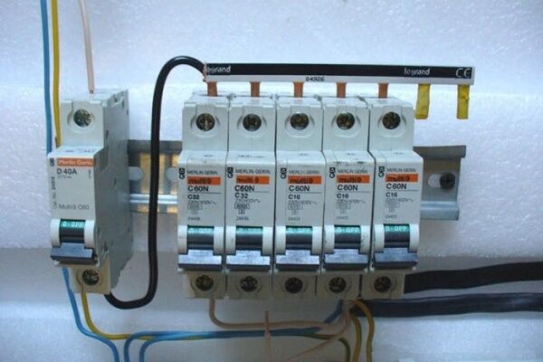
Once you have selected the appropriate circuit breaker, you can begin installing or replacing it.

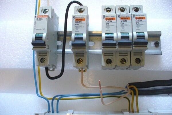
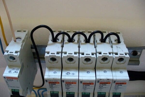
Each element is a module that occupies a number of spaces equal to the number of poles (in the figure there are single-pole samples, i.e. 1 space). The size of one “cell” is 1.75 cm, two – 3.5 cm, etc. Additional information on the selection of switches and the characteristics of different models is presented in this article.
Replacing the circuit breaker in the panel
If you open the electrical panel cover, you will see that all the modules are fixed on a metal strip called a DIN rail. The width of the plate is 3.5 cm, each module occupies 1.75 cm.
To install you will need the following tool:
- pliers;
- screwdrivers - Phillips and straight;
- cable cutting tool, such as wire cutters;
- indicator screwdriver;
- insulation stripper;
- crimper for multi-core cable only.
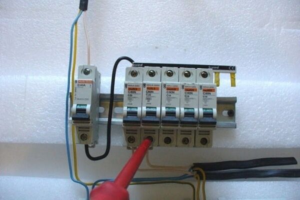
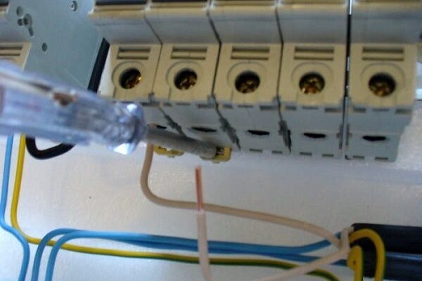
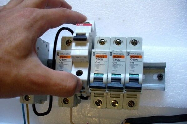
The first thing you should always do before any manipulation in the electrical panel is to turn off the power and make sure that no one accidentally connects the power during operation. To be on the safe side, use an indicator screwdriver and check that there is no voltage.
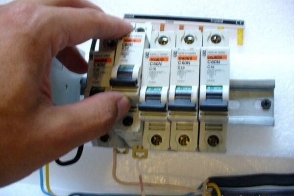
Next, take the circuit breaker you purchased in advance and attach it to the DIN rail so that it fits in line with similar devices.If there is free space left at the edges, then it is better to fix the module with special stops - metal brackets with screws.

Connecting elements with several poles has differences:
- 2-pole – left part: top – phase, bottom – circuit phase; right side: top and bottom – zero;
- 3-pole – the upper parts are the phases in order, the lower parts are the phases of the circuit in the appropriate order;
- 4-pole – like 3-pole, but the rightmost module is zero.
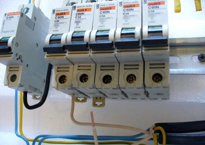
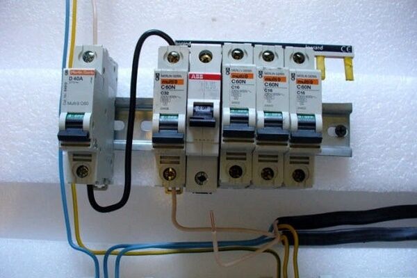
As you can see, the main connection principle is that the input is connected to the upper terminals, the output to the lower ones. The wires are usually routed into the panel. For ease of use, they are grouped using ties.

Having stretched the ends of the wires to the corresponding terminals, position them freely, without tension, and remove the excess with wire cutters. Construction knife or stripper remove part of the insulation — the length of the bare wire is about 1 cm.
If you use a handy tool, try not to damage the cable in the transverse direction, so as not to cause a crease.

The phase connection can be equipped using a comb - a special bus with the required number of poles.Instead of a comb, homemade jumpers made from PV3 wire are also used.
Two wires cannot be placed in one terminal, so they must be crimped with an NShVI tip.

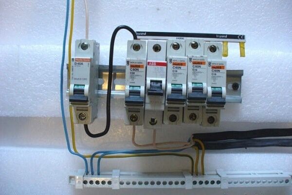
We insert the prepared wires into specially designed holes.

The installation ends with mandatory testing of the system: we apply voltage, connect all devices in the circuit and, using an indicator screwdriver, check the presence of voltage in the area of the upper and lower terminals. Instead of a screwdriver, you can use a multimeter.
According to the rules, the device must be marked to indicate its belonging to a specific circuit. Similar markings should be present on the protective cover of the shield.
Instructions for connecting a two-pole circuit breaker
Now let's try to figure it out connecting a two-pole circuit breaker to a 220 V electrical household circuit. This means that there will be 2 wires at the input - phase and zero.
The wire required for connection has 3 cores with a cross-section of 2.5 mm (VVGngP 3*2.5), therefore, the maximum permissible continuous current is 25 A.
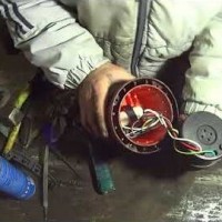
Working elements of the device
We have chosen a two-pole automatic protection device, which looks like this:

There is a hint on the surface of the case - a connection diagram for the machine.

The device is mounted on a metal plate – DIN rail.

Now that we've figured out the components, let's move on to the instructions.
Step-by-step photo instructions for connection
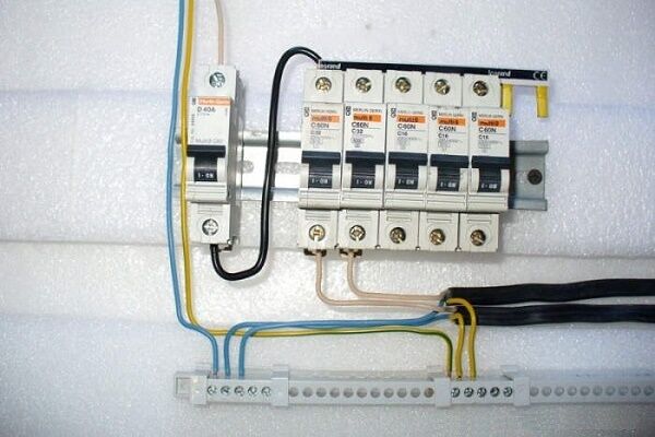
We turn off the voltage in the network and check its absence using a multimeter. We prepare wires that have double insulation. Three wires of different colors are hidden under the layer of external protection. The color correspondence is as follows: black – phase, blue – zero, yellow – ground.

The phase should be on the left, zero should be on the right.Make sure that part of the insulation does not come into contact - when heated, the cable may melt and cause damage to the device. Carefully tighten the screws and proceed to grounding.

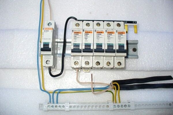
The next step is to connect the outgoing wires, which are attached to the lower terminals.

The connection is complete. All that remains is to apply voltage, move the control lever to the active position and check the operation.
The machine has turned off: what to do?
An inexperienced user when the circuit breaker trips and turning off the lights is in a hurry to restore the operation of household appliances, so he simply opens the protective cover and turns on the device. However, this is not an entirely correct solution; it is better to first find out the reason for the shutdown.
The first thing that needs to be done is to check the connected household units and devices, paying attention to the appearance of sockets and plugs, the presence or absence of the smell of burnt plastic. Forks that are too hot should also be a warning.
One of the common reasons is an increase in energy load. If your washing machine and microwave are working, and when you turn on the vacuum cleaner, the protection is triggered, then an operational overload has occurred. There is only one solution - to evenly distribute the load, that is, turn on powerful devices one at a time.

If the number of devices has not increased, the load has not changed, and a shutdown occurs, the high temperature may be to blame. When the temperature in the panel increases, the machine may also operate.
And the last reason is the failure of the circuit breaker itself. After several reactions to a series of increased currents, short-circuit faults, and arc extinguishing, it becomes unusable, which can be determined by external signs. If the terminals are charred or the plastic has melted, the device must be replaced.
Conclusions and useful video on the topic
The videos provide information that will help you understand the design and connection of the circuit breaker.
Part 1. How to choose a circuit breaker - learning the theory:

Part 2. Instructions on the proper selection of a machine gun:

Step-by-step process for assembling an electrical panel:

Helpful advice from a professional:

As you can see, to connect a circuit breaker, you need to choose the right device, follow a certain installation procedure and observe safety precautions.
If you doubt your abilities or cannot find the reason for the constant protection shutdowns, be sure to contact a qualified electrician.
Trying to install a circuit breaker yourself? Or maybe you don’t agree with the material presented, or you still have questions on the topic? We are waiting for your comments - the contact block is located below.


Very good instructions for a person unfamiliar with electrical installation. Therefore, I would like to “disclose the topic”: maintaining selectivity when installing circuit breakers, in more detail about the schemes for their installation in distribution boards. And most importantly, about installing several switches, about mounting on a DIN rail - not everyone actually knows what this is. And the most important thing - about the PE and N buses - seems to be shown in the photo, but nothing is said about joining them. But this is important.
Good afternoon, Alexander. In order of questions:
1. Electricity supply to apartments and cottages, as a rule, is carried out according to the simplest schemes that do not affect the issues of selectivity of protection.
2. There is no particular variety of schemes for filling apartment and floor panels, and the most common ones are discussed in the articles presented in the section “RCDs and automatic machines”.
3. Installation of several switches is only more labor intensive.
4. The DIN rail is mentioned in the article “Assembling an electrical panel with your own hands.” In fact, it is a metal profile, adapted in shape to mount electrical devices without the use of fasteners. In the mentioned article there is a photo with a rail on which the machines, counter, etc. are located. I have attached a screenshot showing the reverse side of the rail - the technology for fixing the devices is clearly visible.
5. Conductors of group lines intended for grounding and neutralizing household appliances are connected to the PE and N busbars with individual bolts. The section “Grounding and lightning protection” is devoted to grounding and grounding on the site.
Good luck!
The section is called: “RCDs and automatic machines,” but I did not find information about RCDs or differentiated load switches. And I just need to redo the wiring in the apartment and secure the network to the maximum. Therefore, I would like to see possible examples of diagrams for connecting devices in a panel with two cores and without a ground wire (apartment in an old building).
Another question about RCDs: I saw RCD adapters (or adapters) for sockets on sale. This is when the adapter itself is plugged into the outlet, and the plug of the device (for example, a washing machine) is already plugged into it. What is the opinion of experts, will this device be able to protect a person in case of contact with a washing machine whose insulation breaks?
Good afternoon, Roman. I answer the questions in order:
— in the section “UZO and automatic machines” there are over 20 information-rich articles - what specific topic were you missing?
— power supply diagrams for private houses and apartments are discussed in the “Wiring Installation” section - for example, “How to do wiring in an apartment with your own hands from a panel.” Several articles consider the wiring of wooden houses;
- a working RCD socket or RCD plugged into an socket guarantees safety. I would give preference to a “socket with an RCD” - a more reliable connection to the network. By the way, the best option is to allocate a separate line for the washing machine in the apartment panel. Mount the RCD in the panel and connect the line to it.